
Related Manuals for GeoCue TrueView 660

Summary of Contents for GeoCue TrueView 660
- Page 1 GeoCue 1/13/2023 Version 1.0 TrueView 655/660 Hardware Users Guide Version Compatible with LP360 version 2022.1.48 and newer. 1/13/2023...
-
Page 2: Table Of Contents
Notice to users ............................8 Warnings ............................. 8 Disposal .............................. 9 System items ............................ 10 TrueView 655/660 Series payload series product specifications ............ 11 miniVUX-3UAV product specifications ..................12 Camera product specifications ...................... 13 Technical specifications of TrueView 655/660 Series ..............14 System description .......................... - Page 3 TrueView 655/660 Hardware Users Guide Scanner and camera lens/sensor care ....................30 System Configuration File (SCF)......................31 Firmware update ........................... 32 TrueView 655/660 Series Field Operations .................... 33 Base Station ............................33 Pre-Flight ............................34 Disable Obstacle Avoidance ......................34 Center of Gravity (GC) Calibration .....................
-
Page 4: About Geocue
LiDAR processing tools in North America and LP360 is the world’s most widely used tool for exploiting point cloud data. In 2014, GeoCue started a division focused on using small Unmanned Aerial Systems for high accuracy mapping. Leveraging our expertise in... -
Page 5: About Lp360 Drone
TrueView 655/660 Hardware Users Guide ABOUT LP360 DRONE LP360 is a 64-bit Windows® desktop application used for many years by the LP360 Geospatial community for processing traditional aerial, mobile, and terrestrial tripod laser scanner data. The LP360 Drone community is the focus of this Users Guide containing the LP360 workflows for processing and exploiting TrueView, microdrones®... -
Page 6: About Trueview Reckon
Management and automatic delivery of sensor calibration files • Automatic sensor health check • Transfer of sensor Cycle data to GeoCue for technical support • Management of TrueView Points for services that are paid via a metering scheme (marked in this list with $T) •... -
Page 7: Fcc And Ic Compliance
TrueView 655/660 Hardware Users Guide FCC AND IC COMPLIANCE This device complies with Part 15 of the FCC Rules and Industry Canada License-exempt RSS standard(s). Operation is subject to the following two conditions: 1. This device may not cause harmful interference. -
Page 8: Notice To Users
NOTICE TO USERS Warnings Read these warnings carefully before you use TrueView 655/660 payload series. Failure to do so can result in serious injury. Do not attempt to take apart, reassemble, or alter the TrueView 655/660 payload series as it will void the warranty. -
Page 9: Disposal
TrueView 655/660 Hardware Users Guide Do not block the cooling vents located on the right and left side of the payload. If you block the cooling vents the payload will become too hot. WARNING Disposal Do not put batteries or other electrical equipment into general waste containers. Substances in batteries are harmful to human health and the environment. -
Page 10: System Items
Item Quantity TrueView 655/660 Series and TrueView 655/660 Series+ LiDAR TrueView 655/660 Series and TrueView 655/660 Series+ travel case 32GB UMS flash drive (Only use the UMS flash drives provided by GeoCue) (1) (2) AV18 GPS antenna) LiDAR calibration report... -
Page 11: Trueview 655/660 Series Payload Series Product Specifications
Year of release 2022 Mass – TrueView 655 2400 g Mass – TrueView 660 (IMU90) 2500 g Mass – TrueView 660 (IMU82) 2800 g Dimensions 260 x 190 x 158 mm Table 3. TrueView 655/660 Series payload series product specifications. 1/13/2023... -
Page 12: Minivux-3Uav Product Specifications
TrueView 655/660 Hardware Users Guide MINIVUX-3UAV PRODUCT SPECIFICATIONS Technical specifications of TrueView 655/660 Series Laser safety class Field of view Up to 216° Scan speed 100 Hz Scan angle 0.12° Absolute vertical accuracy ± 1 to 5 cm Absolute horizontal accuracy ±... -
Page 13: Camera Product Specifications
Pixel Size: H x V (µm) 2.41 Sensing Area: H x V (mm) 13.2 x 8.80 Focal Length 10.6 mm FOV (individual camera) 63.8° FOV (Combined lateral view cameras) 120° Table 5. TrueView 655/660 Series payload series camera product specifications. 1/13/2023... -
Page 14: Technical Specifications Of Trueview 655/660 Series
104/258 124/308 Table 6. TrueView 655/660 Series payload series technical specifications. (1) Flight Altitude Above Ground Level (AGL) (2) Area coverage is computed for an example of a 20-minute survey (3 minutes for takeoff and landing) at a drone speed of 5 m/s at 56° Field of View (FOV) - Page 15 TrueView 655/660 Hardware Users Guide Average Point Density (ppsm) vs. AGL (m) (90 degree FOV) Speed (m/s) Figure 1. Average Point Density (ppsm) vs AGL (m) (90° FOV). Figure 2. Coverage (acres/hour, 20% dead-time, 5 m/s, 90° FOV). 1/13/2023...
-
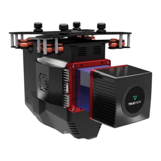
Page 16: System Description
TrueView 655/660 Hardware Users Guide SYSTEM DESCRIPTION This section describes the TrueView 655/660 Series payload series. It addresses how it works, how to set it up, and how to configure the system. Figure 3. TrueView 655/660 Series payload. 1/13/2023... -
Page 17: Trueview 655/660 Series Payload Series Parts
1. Cooling vents (right and left side) 2. Payload interface 3. Scanner 4. Debug port 5. Multifunction button 6. LED lights 7. USB port Table 7. Explanation of TrueView 655/660 Series payload series parts. Figure 5. TrueView 655/660 payload series three GeoCueMapping cameras. 1/13/2023... -
Page 18: Usb Port
TrueView 655/660 Hardware Users Guide USB port The USB port is in the back of the payload. The storage device allows the user to retrieve data after the completed flight. USB port Figure 6. USB port located at the back of the payload. -
Page 19: Ums Drive
TrueView 655/660 Hardware Users Guide UMS drive The TrueView 655/660 Series includes one approved UMS drive with the capacity of 32GB or 64GB flash storage that is proven to have a maximum transfer speed of the USB 3 technology. It is important to only use GeoCue approved UMS drives to make sure the transfer speed is correct, and the data is collected. -
Page 20: Multifunction Button
TrueView 655/660 Hardware Users Guide Multifunction button The multifunction button can be used to start/stop data collection or to abort an operation following the combinations below: Button Press Type Payload Reaction LED Readout Short press Start data collection if payload is SYS LED will switch to a slow initialized (SYS LED is solid green). -
Page 21: Debug Port
The debug port is located on the rear left side of the payload. To access it remove the plastic cover. The debug port is used for service and advanced configuration of the TrueView 655/660 payload series. Do not modify or alter the debug port in any way unless instructed to do so by GeoCue Customer Support. -
Page 22: Led Status Lights
The LED status lights alert the user of the status messages that are in addition to status messages reported by mdCA. Once the power is turned on, there are a total of two LED lights on the front of TrueView 655/660 Series to display the payload status. - Page 23 TrueView 655/660 Hardware Users Guide Table 10 shows all the lighting sequences, LED messages, and their meanings. Table 11 shows how to interpret the symbols in the table. LED Readout Meaning No light No power, or complete to download recording...
- Page 24 TrueView 655/660 Hardware Users Guide Step Action Black circle with a white outline indicates the LED status light is OFF. Starburst of any color indicates the LED status light is blinking. Speed will be indicated by “fast blink” or “slow blink”.
-
Page 25: Procedures
TrueView 655/660 Hardware Users Guide PROCEDURES The images shown in following section are to demonstrate the procedure only. NOTE Attach the payload to the drone Figure 12. Payload front (left), payload back (right). Figure 13. Side views. Payload facing front (left). Payload facing back (right). - Page 26 Do not connect the payload if the connector is damaged, or if dirt or debris cannot be removed. Damage to the payload or drone can occur. Contact GeoCue Customer Service for more assistance.
- Page 27 TrueView 655/660 Hardware Users Guide Figure 15. Release the adapter clip. 6. Make sure the locking mechanism is fully engaged. The locking mechanism is engaged if you cannot see the orange safety arrows on the lock plate. Figure 16. Make sure the payload clips are in the fully extended position.
-
Page 28: Release The Payload From The Drone
TrueView 655/660 Hardware Users Guide Release the payload from the drone To release the payload from the drone: 1. Hold the payload with one hand. 2. Push up on the payload clip and pull the lock plate out into the extended position. -
Page 29: Additional Payload Operation
TrueView 655/660 Hardware Users Guide ADDITIONAL PAYLOAD OPERATION Cleaning As with most optical surfaces, minimal cleaning is the best practice. Any contamination, dust, or debris on the scanner optical surfaces can cause the laser light to diffuse or weaken. This will result in poor data collection. -
Page 30: Pli And Connectors
TrueView 655/660 Hardware Users Guide PLI and connectors The connector on the top of the payload, on the payload adapter on the drone may need cleaning. To clean these connections, it is recommended to only use compressed air. Connectors Figure 18. PLI and connectors. -
Page 31: System Configuration File (Scf)
TrueView 655/660 Hardware Users Guide System Configuration File (SCF) The System Configuration file (SCF), SystemConfiguration.json, must reside on the TrueView USB Mass Storage and is copied into the Cycle\System folder upon creation of each Cycle. The SCF contains information on the calibration parameters of all components for each TrueView system and is used by TrueView EVO to process TrueView data. -
Page 32: Firmware Update
Copy all the files with the .mdpkg and .json extension on the UMS storage device. Power ON the TrueView 655/660 Series payload as you would do for a normal flight. The firmware will install automatically. Allow up to 2 minutes for the process to complete. The two lights on the front of the payload will blink blue for 10 seconds when installation is successful. -
Page 33: Trueview 655/660 Series Field Operations
TrueView 655/660 Hardware Users Guide TRUEVIEW 655/660 SERIES FIELD OPERATIONS 515vB Field Operations Base Station The TrueView 3DIS records GNSS signals during flight which will be corrected later in EVO. This type of system is known as a PPK system. Base station processing methods should be considered during the planning process because the user will need to determine how they plan to correct their flight data before collecting. -
Page 34: Pre-Flight
TrueView 655/660 Hardware Users Guide Pre-Flight Disable Obstacle Avoidance IMPORTANT M300 Only The integration of the TrueView 3DIS system will cause disruption to the M300’s built-in obstacle avoidance detection systems. If these systems are not disabled, they can cause erratic and potentially dangerous behavior including loss of control of the drone. -
Page 35: Center Of Gravity (Gc) Calibration
TrueView 655/660 Hardware Users Guide Center of Gravity (GC) Calibration IMPORTANT M300 Only When heavy payloads are carried on the M300 platform a center of gravity (GC) calibration must be performed there is any change to the payload. This would include if you switched from a TrueView 410 to a TrueView 515 or DJI P1 or even switch to flying without a payload. -
Page 36: Heading Alignment Maneuver
TrueView 655/660 Hardware Users Guide Heading Alignment Maneuver The heading alignment maneuver needs to be done after takeoff, before flying the mission, and after the mission prior to landing for each flight. This maneuver is critical for getting accurate heading corrections for the IMU and will impact the results of the data if not performed. -
Page 37: After Landing
TrueView 655/660 Hardware Users Guide Figure 21. Heading alignment maneuver. After Landing 1. After landing the SYS LED should be flashing white, indicating the system is transferring data. Do not power off the system during this time or it will interrupt the data transfer. -
Page 38: Trueview Mission Checklist
If SYS LED turns to blinking or solid red, it is safe to turn off and move to troubleshoot section or contact GeoCue for further instructions. Remove UMS memory stick and pass to post-processing. -
Page 39: Support
TrueView 655/660 Hardware Users Guide SUPPORT Our searchable support knowledge base contains information on workflows, tips, hints, and probable resolutions to error messages or commonly encountered situations. Normal support business hours are Monday - Friday, 8 AM — 5 PM USA Central Time.
Need help?
Do you have a question about the TrueView 660 and is the answer not in the manual?
Questions and answers