
Related Manuals for Dynisco 1401

Summary of Contents for Dynisco 1401
- Page 1 Instructions for Model 1400/1401 Digital Panel Indicators P/N 974072 04/02 Rev. B ECO # 26719...
-
Page 2: Table Of Contents
ONTENTS Quick Start Instructions ........................3 1. General Information ......................... 5 1.1 Introduction ........................5 1.2 Product Specifications ......................6 1.3 Options ..........................9 1.4 Ordering Guide ........................ 11 2. Installation ..........................11 2.1 Installation ........................11 2.2 Wiring Guidelines ......................12 3. -
Page 3: Quick Start Instructions
1400/1401 Digital Panel Indicators 1400-4-3 Q ODEL UICK TART NSTRUCTIONS OUNTING • Prepare panel cutout to dimensions shown below. • Remove instrument from case by turning captive safety screw (2) counter clockwise. • Grasp the bezel and slide the instrument out of its case. - Page 4 NSTRUMENT ONFIGURATION • Remove instrument from case by loosening safety screw, grab bezel and slide out of case. • Locate jumper V2 in Figure 20, page 21 and place in the open position. • Slide instrument back in case and apply power. Display will now show COnF •...
-
Page 5: General Information
SECTION 2 AND PARTICULARLY SECTION 2.2, E CONCERNING THE EXTERNAL LOADS. NTRODUCTION The 1400 Series is a family of general purpose digital panel indicators developed with the latest technology available today and aimed to reduce costs and improve simplicity during installation and... -
Page 6: Product Specifications
The 1400 comes with a complete availability of ranges from thermocouple, RTD, mV, V and mA input and can also be supplied with three independent alarms. - Page 7 Protection: WATCH DOG circuit for automatic restart DIP SWITCHES for protection against tampering with configuration and calibration parameters Approvals: UL, CSA (1400 only), CE 1.2.2 I NPUTS Three types of inputs are available: J, L, K, R, S, T, N HERMOCOUPLE Type of TC and °C/°F programmable...
- Page 8 DIN 43710-1977 0/+3200°F 0/+1760°C IEC 584-1 0/+3200°F 0/+1760°C IEC 584-1 -150/+750°F -100/+400°C IEC 584-1 0/+2550°F 0/+1400°C IEC 584-1 INEAR NPUT Input Type: See table STANDARD RANGE TABLE Input Type Input Impedance Accuracy 0 - 20 mA 4 - 20 mA...
-
Page 9: Options
1400/1401 Digital Panel Indicators Decimal Point: Programmable in any position RTD (R ESISTANCE EMPERATURE ETECTOR For RTD Pt100 , 3 wire connection with °C/°F selectable. Input: Current injection (100 µA) Input Circuit: Line Resistance: Automatic compensation up to 3 /wire with no measurable error... - Page 10 Type of Alarm: High or low alarms programmable NOTE: The alarm becomes active at the alarm threshold value and will be reset at the alarm threshold value plus or minus the hysteresis value, according to the alarm type. Reset: Automatic or manual, programmable Output of Alarm 1 and 2: Two relays, SPDT Contact Rating:...
-
Page 11: Ordering Guide
1400/1401 Digital Panel Indicators RDERING UIDE Model Code Options Description Code Power Voltage 1400 Thermocouple and RTD input 100 - 240 VAC (switching) Thermocouple and RTD input 24 V AC/DC with dual alarm and linear input 1401 Thermocouple/RTD and linear input... -
Page 12: Wiring Guidelines
IRING UIDELINES Connections are to be made with the instrument housing installed in its proper location. Fig. 4 Rear Terminal Block 1400 Fig. 5 Rear Terminal Block 1401... - Page 13 1400/1401 Digital Panel Indicators OWER Fig. 6 Power Line Wiring From 100 V to 240 V AC or LINE 24 V AC/DC NOTE: 1) To avoid electric shock, connect power supply at the end of the wiring procedure only. 2) The power supply input has no fuse protection. Please provide it externally.
- Page 14 THERMOCOUPLE COMPENSATING CABLE COLOR CODES Thermocouple British American German French Material BS 1843 ANSI MC 96.1 DIN 43710 NFE 18-001 Copper White Blue Yellow Constantan Blue Brown Blue Blue Blue Brown Blue Iron Yellow White Yellow Constantan Blue Blue Black Black Black Blue...
- Page 15 1400/1401 Digital Panel Indicators NOTE: 1) Don’t run input wires together with power cables 2) Use proper cable, preferably shielded 3) Pay attention to the line resistance; a high line resistance may cause measurement errors. 4) If shielded cable is used, the shield should be grounded at one point only (see Fig. 9) RTD Input Fig.
- Page 16 Fig. 11 Alarm 2 Relay Wiring The relay output is an SPDT relay, without snubber network. The contact ratings are: 3 A/30 V DC on resistive load or 3 A/250 V AC on resistive load. The MTBF is 2 x 10 at specified rating.
- Page 17 1400/1401 Digital Panel Indicators Fig. 13 External Protection for Inductive Load Greater than 40 mA AC The value of capacitor (C) and resistor (R) are shown in the following table. INDUCTIVE RESISTOR OPERATING LOAD (µF) POWER (W) VOLTAGE <40 mA 0.022...
-
Page 18: Instrument Configuration
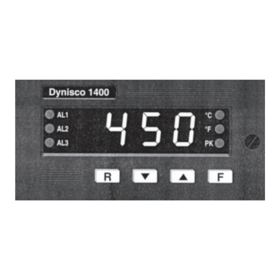
NALOG ETRANSMISSION UTPUT IRING For mA output the maximum load is equal to 500 V. For V output the minimum load is equal to 5 kV. Fig. 15 Analog Retransmission Output Wiring NSTRUMENT ONFIGURATION RONT ANEL ESCRIPTION Fig. 16 Front View Digital Panel Indicator 3.1.1 I NDICATORS AL1 - AL2 - AL3... -
Page 19: Instrument Configuration
1400/1401 Digital Panel Indicators 3.1.2 D ISPLAY The display continuously shows the measured value in eng. units. During configuration and calibration set up, this display is used to show parameter’s name and the relative value. 3.1.3 K EYBOARD ESCRIPTION Increases the parameter value or to display the peak high value. - Page 20 Fig. 17 Jumpers for Analog Input 2) The instrument is shipped with a 20mA ( standard) analog retransmission (when fitted). When it is desired to use a 10 V analog retransmission, the solder jumpers should be set properly in accordance with the table below. Output Type SH 5 SH 6...
- Page 21 1400/1401 Digital Panel Indicators setting. Set SH2 and CH2, for thermocouple input only, in accordance with the following table if underrange is desired. Indication open close overrange (STD) close open underrange Fig. 19 Jumpers for Lead Break Indication Configuration Procedure 1) Remove the instrument from its case.
- Page 22 TC type range -100/+900°C TC type range -100/+1000°C TC type range -100/+1370°C TC type range -100/+400°C TC type range 0/+1400°C TC type range 0/+1760°C TC type range 0/+1760°C RTD type Pt 100 range -200/+600°C RTD type Pt 100 range -199.9/+600°C Linear...
- Page 23 1400/1401 Digital Panel Indicators Linear 1 - 5 V Linear 2 - 10 V TC type range -150/+1650°F TC type range -150/+1850°F TC type range -150/+2500°F TC type range -150/+750°F TC type range 0/+2550°F TC type range 0/+3200°F TC type range 0/+3200°F...
- Page 24 Low alarm with automatic reset High alarm with manual reset Low alarm with manual reset Alarm 1 action Available only when P6 is other than OFF. reverse (relay de-energized in alarm condition) direct (relay energized in alarm condition) Stand by of alarm 1 Available only when P6 is other than OFF.
- Page 25 1400/1401 Digital Panel Indicators P14 = Stand by of alarm 2 Available only when P12 is other than OFF OFF = stand by disabled stand by enabled NOTE: The alarm stand by function operates as follows: It inhibits an alarm condition at start up.
-
Page 26: Operating Instructions
P20 = Safety lock Device unlocked. All the parameters can be modified during operating mode. Device locked. No parameter can be modified. 2 to 999 = Select a code (to be remembered) and during the “operating mode” and scrolling the “software key”... -
Page 27: Operating Mode
1400/1401 Digital Panel Indicators PERATING The alarm parameters and set-up procedure are checked by a time out of approximately 10 seconds. If during this time no other push-button has been pushed, the display will return to show the measured variable and the changes will not be stored. - Page 28 4.2.4 P IGH AND The Model 1400 stores the maximum and the minimum measured values continuously: To display the maximum measured value, push the pushbutton, the “PK” LED will light up and the display will show the maximum measured value.
-
Page 29: Loading Default Parameters
1400/1401 Digital Panel Indicators OADING EFAULT ARAMETERS RELIMINARY The instrument is supplied with a default parameter set (already stored) which can override all parameters at any time. There are parameter sets for configuration mode and parameter sets for operating mode. -
Page 30: Loading Default Operating Parameters
OADING EFAULT PERATING ARAMETERS During the run time, when the display shows the measured value, it is possible to load the default data for operative parameters: 1) Push push-button at the same time; the display will show “dF.OF” 2) Push the push-button;... -
Page 31: Repair
For technical assistance please call 800-221-2201 or 508-541-9400 or fax 508-541-9436. ARRANTY This Dynisco product is warranted under terms and conditions set forth in the Dynisco Web Pages. Go to www.dynisco.com and click on “Warranty” at the bottom of any page for complete details. - Page 32 OTES...
- Page 33 OTES...
- Page 34 OTES...
- Page 35 CITY _____________________________ STATE _____________ ZIP __________________ COUNTRY _____________________________________________________________________ TELEPHONE _____________________________ FAX ________________________________ My application is _______________________________________________________________ Is this your first purchase from Dynisco? YES __________ NO __________ How did you first hear of Dynisco? ADVERTISING ________ REP __________ PREVIOUS USE ___________ COLLEAGUE _____________ DIRECTORY ______________...
- Page 36 Place Stamp Here DYNISCO INSTRUMENTS 38 FORGE PARKWAY FRANKLIN, MA 02038 ATTN: MARKETING DEPT.
Need help?
Do you have a question about the 1401 and is the answer not in the manual?
Questions and answers