Table of Contents
Advertisement
Quick Links
electric
Gialix
Range :
Gialix
MA -
(Ref. : 13141 )
Gialix
MA
f. : 13141 )
Gialix
MA -
(Ref. : 131
Gialix 1
- 400 V
(Ref. : 131
Gialix
MA -
(Ref. : 1314
Production site
Rue de la République
80210 Feuquières en Vimeu
Tel : 03.22.61.21.00.
Fax : 03.22.30.01.19.
RC Abbeville B 722 041 845
V
400 V
V
)
)
400 V
)
Ref. 1871067 / 0408351
Spare parts department
Tel : 03.22.61.21.21.
Fax : 03.22.30.01.19.
MA
kW
Advertisement
Table of Contents
Troubleshooting

Related Manuals for Gialix 48 MA


Summarization of Contents
1 - GENERALITIES
1.1 - DESCRIPTION
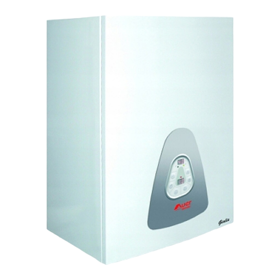
Description of Gialix range boilers, heating chamber, control panel, and hydraulic components.
1.1.1 - Setting for low temperature application
Instructions for setting the boiler for low temperature applications, particularly for underfloor water circuits.
1.1.2 - Maximum temperature settings summary
Summary of maximum boiler temperature settings and safety cut-out for different heating applications.
2.1 Basic Hydraulic Circuits
2.1.1 Direct heating circuit
Diagram and explanation of a direct heating circuit without a mixing valve, including component references.
2.1.2 1 Direct heating circuit with DHW
Diagram and explanation of a heating circuit with DHW, including optional 3-way valve or pumps.
2.3 Installation
2.3.1 Hydraulic Connections
Dimensional drawings showing hydraulic connections for 36-72 kW and 120 kW models, including front and side views.
2.3.2 Location
Guidelines for boiler positioning, including wall mounting height and clearance requirements.
2.3.3 Wall mounting
Instructions for wall mounting, including removing the front panel for access.
2.3.3.2 Wall fixing
Detailed diagrams showing wall fixing points and dimensions for 36-72 kW, 120 kW, and 196 kW models.
2.4 CONNECTIONS
2.4.1 Hydraulic Connection
Illustration showing the location of outgoing (D) and return (R) hydraulic connections on the top of the boiler.
2.4.2 Electric Connections
General instructions for making electric connections, emphasizing tightening and safety precautions.
2.4.2.1 Absorbed Intensity and Wire Diameters
Table of absorbed intensities and required power supply wire diameters and fuse ratings for each boiler model.
2.4.2.2 Power Terminals
Instructions and diagrams for connecting power supply wires to the terminals for 36-72 kW and 120 kW models.
2.4.2.3 Electric Connection
Wiring diagrams illustrating the connection of power supply cables and earth for 36-72 kW, 120 kW, and 196 kW models.
2.4.2.4 Wiring Diagrams
Detailed wiring diagram for Gialix 36 and 48 kW models, including color codes and component references.
2.4.2.5 Connection of Accessories
Instructions for connecting accessories like thermostats, sensors, pumps, and diverter valves to the boiler terminals.
2.4.2.6 Connection of Load Shedding Devices
Diagrams showing how to connect load shedding devices for 36-48 kW and 72-196 kW models.
2.4.2.7 Internal Wiring Diagrams
Internal wiring diagram for 36 kW and 48 kW models, detailing connections to the transformer and electronic card.
2.4.2.8 Power Adjustment
Procedure for adjusting the boiler's power output to values other than the nominal, with specific parameter settings.
2.5 Starting the Boiler
2.5.1 Filling the Installation
Step-by-step guide for filling the boiler and installation with water, including pressure checks and bleeders.
2.5.2 Control Settings
Instructions for accessing and modifying boiler parameters using the control panel buttons and displays.
2.5.2.1 Parameters List
Comprehensive list of boiler parameters, their descriptions, available settings, and ex-work configurations.
2.5.2.2 Adjusting to Other Power
Detailed table and procedure for adjusting the boiler's power output by modifying specific parameters.
2.5.3 HEATING DIAGRAM
Section detailing heating diagrams for various system types and temperature settings.
2.5.3.1 Floor Heating
Heating diagram for floor heating systems, illustrating the relationship between outside temperature and requested boiler outflow temperature.
2.5.3.2 Radiators
Heating diagram for radiator systems, showing temperature settings for different conditions.
2.5.3.3 Installation Heating Diagram
Blank graph for creating custom installation heating diagrams.
2.5.4 Timer Input Parametering
Explanation of parameter settings for timer input, affecting DHW production and frost protection.
2.5.5 Temperatures Display
Description of how boiler temperatures and sensor statuses are displayed on the control panel.
2.5.6 Ambience Requested Temperature Adjustment
Guide on adjusting requested temperature using ambience sensors and control panel functions.
2.6 Maintenance and Troubleshooting
2.6.1 Meters Display
Instructions on how to access and read the heating cycle meters for each contactor on the boiler.
2.6.2 Maintenance
Recommendations for annual boiler checks by a qualified technician and regular inspection of electric connections.
2.6.3 Troubleshooting
Table outlining common boiler troubles, probable reasons, and step-by-step troubleshooting procedures.
2.6.4 Failures Display
Explanation of error codes and blinking warnings displayed for sensor or pressure failures, and their impact on boiler operation.
2.6.5 Temperature Sensors
Technical data tables showing ohmic values for boiler, DHW, outside, and ambience temperature sensors at various temperatures.
Need help?
Do you have a question about the 48 MA and is the answer not in the manual?
Questions and answers