Table of Contents
Advertisement
Quick Links
EVB90109
MLX90109 Evaluation Board Manual
Features
Minimum PCB size (30 * 30 mm) including a MLX90109 transceiver IC and an optimized antenna
Tuned resonance frequency to 125kHz
Modulation network on board for a maximum flexibility
Setup for fast On/Off keying modulation mode
DIL-10 footprint for easy mounting on prototype set up and development kit
Ordering Information
Part No.
EVB90109
Application Examples
Car Immobilizers
Portable readers
Battery powered door locks
Access control
House held appliances
General Description
The EVB90109 is an assembled module that allows evaluating the advantages of the MLX90109
transceiver IC. It will facilitate the starts of RFID applications and can be implemented in a compact
way, with minimum development time, and minimum final system cost. All pins of the MLX90109
reader are available on a DIL socket for easy control with an external microcontroller. Two extra pins
have been added for extended control options on the voltage on the MODU pin.
The EVB90109 can be used as a 125 kHz reader, to read out the load modulation from a transponder. It
can also be used to send information to a transponder using On/Off keying modulation. For fast
protocol which required fast fall time on the reader's antenna, the EVB90109 includes a "Fast decay"
circuit composed of an external transistor and diode in parallel on the antenna. This circuit is
accessible through a digital pin on the DIL-10 connector.
REVISION 006 - JUNE 20, 2017
390129010901
Evaluation Board
Advertisement
Table of Contents

Related Manuals for Melexis MLX90109


Summary of Contents for Melexis MLX90109
-
Page 1: Features
MODU pin. The EVB90109 can be used as a 125 kHz reader, to read out the load modulation from a transponder. It can also be used to send information to a transponder using On/Off keying modulation. For fast protocol which required fast fall time on the reader’s antenna, the EVB90109 includes a “Fast decay”... -
Page 2: Table Of Contents
2.6. Antenna voltage in 100% modulation operation ................5 2.7. Fast decay circuit ..........................6 3. Schematic .............................. 7 4. Physical outline ............................8 5. Pinning of the EVB90109 ........................9 6. Components ............................9 7. Contact ..............................10 8. Disclaimer ............................10... -
Page 3: Evb90109 Electrical Specifications
2. Description 2.1. General explanation The EVB90109 consists of a single chip inductive RFID reader for the 125 kHz frequency range with an external inductance (L) and capacitance (C) connected as a parallel resonant circuit. The antenna voltage amplitude can be set On/Off externally with the digital line MODUR2, which controls a resistive and capacitive network called “Modulation network”... -
Page 4: Parallel Antenna
2.2. Parallel antenna The parallel antenna of the EVB90109 consists of the inductance (L) of the reader coil and the tune capacitor (C4), which form a resonant system at 125 kHz with a total (inductance and capacitance) antenna impedance of about 1.3kOhms. -
Page 5: Noise Cancellation In Read Operation
OFF the magnetic field depend on the quality factor (Qant) of the parallel antenna connected to the reader (about 24 periods with the EVB90109). To reduce this fall time, the “fast decay” circuit can be used. Page 5 of 10... -
Page 6: Fast Decay Circuit
Very small fall time may be required in fast protocol, to be understood by the transponder in the field. This is why, the EVB90109 include a “fast decay” circuit controlled through the pin FAST_DECAY and composed of the transitstor Q1 and the diode D1. -
Page 7: Schematic
EVB90109 MLX90109 Evaluation Board Manual 3. Schematic The following diagram shows the schematic of the EVB90109. All components in grey are not mounted but the footprints are present if the user wants to use it for dedicated applications. 4 Fast_Decay... -
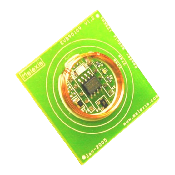
Page 8: Physical Outline
EVB90109 MLX90109 Evaluation Board Manual 4. Physical outline The following figure shows the outline of the MLX90109 evaluation board. Coil DIL-10 DIL-10 MLX90109 Figure 3: EVB90109 outline: top side Page 8 of 10 REVISION 006 - JUNE 20, 2017 390129010901... -
Page 9: Pinning Of The Evb90109
Modulation Network MODUR2 Modulation Network MODE Decoding selection CLOCK Clock signal DATA Decoded data Power Supply Table 2: Pinning of the EVB90109 6. Components Reference Value Description 39 kohms Modulation network 8.2 kohms Modulation network Not mounted Additional resistor for the modulation network... -
Page 10: Contact
8. Disclaimer The information furnished by Melexis herein (“Information”) is believed to be correct and accurate. Melexis disclaims (i) any and all liability in connection with or arising out of the furnishing, performance or use of the technical data or use of the product(s) as described herein (“Product”) (ii) any and all liability, including witho ut limitation, special, consequential or incidental damages, and (iii) any and all warranties, express, statutory, implied, or by description, including warranties of fitness for particular purpose, non- infringement and merchantability.
Need help?
Do you have a question about the MLX90109 and is the answer not in the manual?
Questions and answers