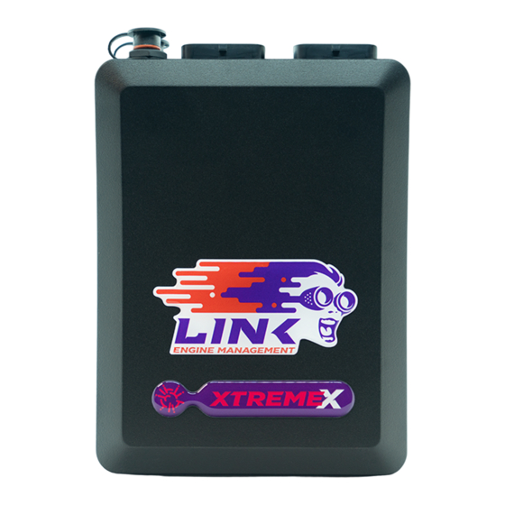
Summarization of Contents
Introduction
Support Options
Provides contact points for technical assistance and troubleshooting.
Choosing a Configuration
Injector Outputs
Details the capabilities and specifications of injector drive channels.
Ignition Outputs
Explains the functions and limitations of ignition output channels.
Auxiliary Outputs
Describes the versatility and constraints of general-purpose auxiliary outputs.
Analog/Temperature Inputs
Covers the use and specifications of analog voltage and temperature inputs.
Digital Inputs
Outlines the functionality and limitations of digital input channels.
Trigger Inputs
Explains the role of trigger inputs for engine speed and position calculation.
Summary
Provides a quick overview and configuration example for common setups.
Installer IO Table
A table detailing input/output assignments for specific configurations.
Component Installation Locations
ECU Location
Guidelines for selecting an optimal and safe mounting location for the ECU.
Ignition Component Placement
Recommendations for positioning ignition system components to minimize interference.
MAP Sensor Location
Guidance on selecting an appropriate location for the MAP sensor.
Power and Ground Wiring
Power Supplies
Details the recommended wiring arrangement for ECU power supplies.
+14V In
Explains the function and connection requirements for the main +14V input.
+14V Aux9/10
Describes the +14V auxiliary power supply for specific ECU outputs.
Power Ground
Guidelines for correctly wiring power ground connections for high current loads.
Sensor Ground
Explains the importance of correct sensor ground wiring for stable readings.
+5V Out
Details the regulated +5V output for powering sensors.
+8V Out
Details the regulated +8V output for sensors like Crank Angle Sensors.
ECU Hold Power Wiring
Describes a wiring method to keep the ECU powered after ignition off.
Input Signal Wiring
Trigger Inputs
Explains how trigger inputs calculate engine speed and position.
Reluctor/Magnetic Sensors
Details wiring and polarity for reluctor/magnetic type trigger sensors.
Hall/Optical/Proximity Sensors
Covers wiring for hall effect, optical, and proximity trigger sensors.
MAP Sensor
Information on connecting and wiring Manifold Absolute Pressure sensors.
TPS Wiring
Instructions for wiring the Throttle Position Sensor for load sensing and other functions.
Engine Coolant Temperature Sensor
Details wiring for engine coolant temperature sensors (thermistor or 0-5V).
Intake Air Temperature Sensor
Explains wiring for intake air temperature sensors for fuel/ignition correction.
Narrow Band Oxygen Sensor
Covers wiring and use of narrow band oxygen sensors for closed loop lambda.
Wide Band Oxygen Sensor
Details connecting wideband oxygen sensor controllers for accurate AFR measurement.
GP Pressure & Temperature Sensing
How to use analog inputs for general purpose pressure/temperature sensors.
Digital Input Wiring
Instructions for wiring digital inputs for switches and sensors.
Output Wiring
Fuel Injector Drives
Explains wiring for fuel injector outputs and considerations for impedance.
High Impedance Injectors
Details wiring high impedance injectors to ECU injector drives.
Low Impedance Injectors
Covers wiring low impedance injectors and the need for ballast resistors.
Injection Mode
Describes available injection modes like Sequential and Group.
Ignition Drives
Explains the use of ignition drives for various ignition system configurations.
Igniter Requirements
Details the role and wiring of igniters as an interface to ignition coils.
Coil Requirements
Discusses coil selection and dwell time for optimal spark energy.
Ignition System Wiring
General guidelines for wiring ignition systems, including suppression.
Distributor Ignition
Explains wiring for traditional distributor-based ignition systems.
Multi-Coil Wasted Spark Ignition
Details wiring for wasted spark ignition using dual post coils.
Multi-Coil Direct Spark Ignition
Covers wiring for direct spark ignition systems with individual coils.
Auxiliary Output Wiring
Explains how to use auxiliary outputs for various engine functions.
Low Side Driving (Switching To Ground)
Describes wiring auxiliary outputs to ground for actuating loads.
High Side Driving (Switching Power Supply)
Details using auxiliary outputs to supply power to loads.
Switching Through a Relay
How to use relays with auxiliary outputs for high-current loads.
Switching an LED
Wiring LEDs to auxiliary outputs for indicators or warning lights.
Idle Speed Control
Two Terminal ISC Solenoid
Wiring instructions for two-terminal Idle Speed Control solenoids.
Three Terminal ISC Solenoid
Details wiring for three-terminal ISC solenoids.
Four Terminal ISC Stepper Motor
Wiring instructions for four-terminal Idle Speed Control stepper motors.
Six Terminal ISC Stepper Motor
Covers wiring for six-terminal ISC stepper motors.
Rotary Engine Wiring
Rotary Injection Wiring
Specific injector wiring configurations for rotary engines.
Rotary Ignition Wiring
Specific ignition wiring configurations for rotary engines.
Metering Oil Pump Wiring
Details wiring for rotary engine metering oil pump control.
PC Tuning
Installing USB Drivers
Steps for installing necessary USB drivers for ECU communication.
Installing PCLink Tuning Software
Instructions for downloading and installing the PCLink tuning software.
Communicating With Your ECU
Procedure for establishing a connection between the ECU and PC.
First Time Setup
Pre-start Checks
Essential checks to perform before configuring or starting the ECU.
Initial Setup
Basic configuration steps for the ECU, including fuel and ignition.
Trigger Calibration
Calibrating trigger inputs to accurately measure engine position.
First Time Startup
Procedure for starting the engine for the first time after setup.
Essential Tuning Adjustments
Details critical ECU parameters for initial engine tuning.


Need help?
Do you have a question about the G4 Xtreme and is the answer not in the manual?
Questions and answers