Table of Contents
Advertisement
OWNER'S OPERATION AND INSTALLATION MANUAL
Patent Pending
WARNING: If the information in this manual is not fol-
lowed exactly, a fire or explosion may result causing
property damage, personal injury or loss of life.
— Do not store or use gasoline or other flammable
vapors and liquids in the vicinity of this or any other
appliance.
— WHAT TO DO IF YOU SMELL GAS
• Do not try to light any appliance.
• Do not touch any electrical switch; do not use any
phone in your building.
• Immediately call your gas supplier from a neighbor's
phone. Follow the gas supplier's instructions.
• If you cannot reach your gas supplier, call the fire
department.
— Installation and service must be performed by a quali-
fied installer, service agency or the gas supplier.
INSTALLER: Leave this manual with the appliance
CONSUMER: Retain this manual for future reference.
For more information, visit www.desatech.com
DIRECT-VENT FIREPLACE
NATURAL GAS MODELS
(V)TC36N(-HA) SERIES
PROPANE/LP GAS MODELS
(V)TC36P(-HA) SERIES
Advertisement
Table of Contents

Subscribe to Our Youtube Channel
Related Manuals for Desa (V)TC36N(-HA) Series, (V)TC36P(-HA) Series

Summary of Contents for Desa (V)TC36N(-HA) Series, (V)TC36P(-HA) Series
- Page 1 DIRECT-VENT FIREPLACE OWNER’S OPERATION AND INSTALLATION MANUAL Patent Pending PROPANE/LP GAS MODELS WARNING: If the information in this manual is not fol- lowed exactly, a fire or explosion may result causing property damage, personal injury or loss of life. — Do not store or use gasoline or other flammable vapors and liquids in the vicinity of this or any other appliance.
-
Page 2: Table Of Contents
Safety Information ... 2 Product Identification ... 4 Local Codes... 4 Product Features ... 5 Pre-Installation Preparation ... 5 Location of Termination Cap ... 8 Venting Installation Instructions ... 9 Fireplace Installation... 19 Operating Fireplace ... 27 Inspecting Burners... 30 WARNING: Improper in- stallation, adjustment, al- teration, service or main-... - Page 3 SAFETy INFORMATION Continued This fireplace must be installed by a qualified (cer- tified or licensed) service person. It has a sealed gas combustion chamber that uses a coaxial pipe (pipe within a pipe and having the same center) venting system. It brings in fresh air for combus- tion through the outer pipe and combustion gases are exhausted through the inner pipe.
-
Page 4: Product Identification
SAFETy INFORMATION Continued 2. If you smell gas • shut off gas supply • do not try to light any appliance • do not touch any electrical switch; do not use any phone in your building • immediately call your gas supplier from a neighbor’s phone. -
Page 5: Product Features
LOCATION AND SpACE REqUIREMENTS Determine the safest and most efficient location for your DESA direct-vent fireplace. Make sure that rafters and wall studs are not in the way of the venting system. Choose a location where the heat output is not affected by drafts, air conditioning ducts, windows or doors. -
Page 6: Framing And Finishing
PRE-INSTALLATION PREPARATION Continued • If recessing into a wall, you can avoid extra framing by positioning your fireplace against an already existing framing member. • Do not recess termination cap into a wall or siding. • You may paint the termination cap with 450º F (232º... - Page 7 PRE-INSTALLATION PREPARATION Continued " 15" " " 41" " " Figure 5 - Framing Clearances for Corner Installation 116192-01G " " Top of Louver Nailing Nailing Tabs Tabs Ref. Figure 6 - Clearances for Combustible www.desatech.com Wall Opening Mantel from Mantel Top of Louver Depth...
-
Page 8: Location Of Termination Cap
LOCATION OF TERMINATION CAP Fixed Closed Openable TERMINATION CAP A = clearance above grade, veranda, porch, deck, or balcony [*12" (30.5 cm) minimum] B = clearance to window or door that may be opened [6" (15 cm) min. for 10,000 Btu or less; 9" (23 cm) in US if between 10,000 and 50,000, 12"... -
Page 9: Venting Installation Instructions
These models are tested and approved for use with DESA (direct-vent) pipe components and terminations. The venting system must terminate on the outside of the structure and can not be attached to a chimney or flue system serving a separate solid fuel or gas burning appliance. -
Page 10: Venting Installation Instructions
VENTING INSTALLATION INSTRUCTIONS Continued INSTALLATION pLANNING There are two basic types of direct-vent in- stallation: • Horizontal Termination • Vertical Termination Horizontal Termination Installation IMPORTANT: Horizontal square terminations require only inner portion of wall firestop. Hori- zontal installations using round termination require exterior portion of wall firestop (see Figure 14, page 12). - Page 11 VENTING INSTALLATION INSTRUCTIONS Continued WARNING: Do not recess vent termination into any wall. This will cause a fire hazard. Noncombustible Exterior Wall: horizontal vent cap in the center of the 8 round hole and attach to the exterior wall with four wood screws provided.
- Page 12 VENTING INSTALLATION INSTRUCTIONS Continued Minimum Pipe Overlap 1 " Direct-Vent Pipe Wall Firestop Maintain 1" Minimum Air Space Around Outer Pipe When Penetrating a Wall " x 10 " Framed Opening Exterior Wall with Vinyl Siding Figure 13 - Typical Horizontal Termination Cap Mounting with Additional Siding Standoff Installed Horizontal Termination Configurations...
- Page 13 VENTING INSTALLATION INSTRUCTIONS CORNER INSTALLATION Recommended Applications: • Corner ground floor installation • Ground floor installation where pipe vents horizon- tally through wall (over 12" horizontal pipe) • Basement installation where one foot clearance from ground to termination is possible Not to Exceed (H) Limits Square Termination...
- Page 14 VENTING INSTALLATION INSTRUCTIONS HORIZONTAL SYSTEM INSTALLATION USING TWO 90° ELBOWS The following configurations show the minimum vertical rise requirements for a horizontal system using two 90° elbows. Venting with Two 90° Elbows Vertical (V) Horizontal (H 5' min. 2' max. 6' min.
-
Page 15: Installation For Vertical Termination
VENTING INSTALLATION INSTRUCTIONS Continued INSTALLATION FOR vERTICAL TERMINATION Note: Vertical restrictor must be installed in all vertical installations. 1. Determine the route your vertical venting will take. If ceiling joists, roof rafters or other framing will obstruct the venting system, consider an offset (see Figure 19) to avoid cut- ting load bearing members. - Page 16 VENTING INSTALLATION INSTRUCTIONS Continued 5. Place the flashing over the pipe section(s) extending through the roof. Secure the base of the flashing to the roof and framing with roof- ing nails. Be sure roofing material overlaps the top edge of the flashing as shown in Figure 19, page 15.
-
Page 17: High Altitude Installation
Figure 24 - Vertical Venting Configuration With No Horizontal Run (Vertical Round Horizontal (H) HIGH ALTITUDE INSTALLATION 6' max. Your DESA direct-vent fireplace has been tested and 12' max. approved for elevations from 0-2000 feet (USA) and 18' max. elevations from 0-4500 feet (Canada). - Page 18 Elbow 12" Extension Figure 25 - Recommended 12" Extension for High Altitude Installation PARTS LIST FOR VENTING KITS AND COMpONENTS DESA (5"/8") Pipe & Vent Kits Number Description P58-6 6" Section Double Wall Pipe, Galvanized P58-12 12" Section Double Wall Pipe,...
-
Page 19: Fireplace Installation
FIREPLACE INSTALLATION CHECK GAS TYPE Use proper gas type for the fireplace unit you are installing. If you have conflicting gas types, do not install fireplace. See retailer where you purchased the fireplace for proper fireplace according to your gas type or to purchase gas conversion kit (see Accessories, page 42). - Page 20 FIREPLACE INSTALLATION Continued CAUTION: Never touch the blower wheel while in operation. 9. Check to make sure that the power cord is com- pletely clear of the blower wheel and that there are no other foreign objects in blower wheel. Turn blower on and check for operation.
- Page 21 FIREPLACE INSTALLATION Continued 7. Check to make sure that the power cord is com- pletely clear of the blower wheel and that there are no other foreign objects in blower wheel. Also double check all wire leads and make sure wire routing is not pinched or in a precarious position.
- Page 22 FIREPLACE INSTALLATION Continued CAUTION: Use only new, black iron or steel pipe. Inter- nally-tinned copper tubing may be used in certain areas. Check your local codes. Use pipe of 1/2" diameter or greater to allow proper gas volume to fireplace. If pipe is too small, undue loss of volume will occur.
-
Page 23: Checking Gas Connections
FIREPLACE INSTALLATION Continued To Gas Supply (Natural) Equipment Shutoff Valve To External Regulator (Propane/LP) Flexible Gas Line Do NOT Kink Control Valve Figure 33 - Connecting Flexible Gas Line to Millivolt Valve CHECKING GAS CONNECTIONS WARNING: Test all gas piping and connections, internal and external to unit, for leaks after installing or servicing. - Page 24 FIREPLACE INSTALLATION Continued pRESSURE TESTING FIREpLACE GAS CONNECTIONS 1. Open equipment shutoff valve (see Figure 34, page 23). 2. Open propane/LP supply tank valve for propane/LP fireplace or main gas valve located on or near gas meter for natural gas fireplace.
- Page 25 FIREPLACE INSTALLATION Continued Installing 9-Volt Alkaline Battery in Hand- Held Remote Control Unit 1. Remove battery cover on back of remote control unit. 2. Attach terminal wires to a 9-volt alkaline battery (not included). Place battery into the battery housing. 3.
-
Page 26: Brick Panels
FIREPLACE INSTALLATION Continued 4. Remount the new frame at the hinge with five new screws before closing door. This will ensure seating of the gasket. 5. Close glass door frame. Lock latches by placing the bar under the tab on door and pushing down and back on latch (see Figure 42, page 25). -
Page 27: Operating Fireplace
FIREPLACE INSTALLATION Continued 6. Install rear brick panel first. Rest bottom edge of panel on back edge of burner assembly (see Figure 44). 7. Install left side brick panel by sliding it be- tween the burner assembly and the side of the firebox (see Figure 44). -
Page 28: Operating Fireplace
OPERATING FIREPLACE Continued 7. Turn gas control knob counterclockwise to PILOT (see Figure 45) 8. Push in gas control knob all the way and hold. Immediately light the pilot by repeat- edly depressing the piezo spark ignitor until a flame appears. Continue to hold for about one (1) minute after the pilot is lit. - Page 29 OPERATING FIREPLACE Continued ON/OFF SERIES MODEL HRC100 Hold the control button on the hand-held remote until burner turns on. Hold the con- trol button again until burner turns off (see Figure 47). TO LOCK press both buttons on hand-held remote control until light stops flashing. Hand- held remote control is now locked.
-
Page 30: Pilot Assembly
OPERATING FIREPLACE Continued Key Pad Lock Feature This feature allows the user to lock/unlock the keypad on the hand-held remote in the MANU or AUTO mode to prevent inadvertent operation (i.e. children operating the hand-held remote control, etc.). The keypad is locked in either on or off. Press the POWER and LOCK buttons together to turn the unit on or off. -
Page 31: Burner Flame Pattern
INSPECTING bURNERS Continued BURNER FLAME PATTERN Burner flames will be steady; not lifting or floating. Flame patterns will be different from unit to unit and will vary depending on installation type and weather conditions. If the vent configuration is installed incorrectly, the flames will lift or "ghost". -
Page 32: Venting System
CLEANING AND MAINTENANCE Continued CAUTION: Do not vacuum if pieces are hot. Use only the tempered glass door replacement intended for this fireplace (see Replacement Parts, page 37 for detail on ordering). No substitutions may be made. See Removing/Replacing Glass Door, page 25 for instructions for replacing glass door. -
Page 33: Troubleshooting
WARNING: Turn off heater and let cool before servicing. Only a qualified service person should service and repair heater. CAUTION: Never use a wire, needle or similar object to clean pilot. This can damage pilot unit. Note: All troubleshooting items are listed in order of operation. OBSERVED PROBLEM When ignitor button is pressed, there is no spark at pilot... - Page 34 OBSERVED PROBLEM Pilot lights but flame goes out when control knob is released Burner does not light after pilot is lit Delayed ignition burner Burner backfiring during com- bustion Slight smoke or odor during initial operation TROUbLESHOOTING Continued POSSIBLE CAUSE 1.
- Page 35 OBSERVED PROBLEM Heater produces a whistling noise when burner is lit Glass soots Fireplace produces a clicking/tick- ing noise just after burners are lit or shut off Remote does not function 116192-01G TROUbLESHOOTING Continued POSSIBLE CAUSE 1. Turning gas control knob to HI position when burner is cold 2.
- Page 36 WARNING: If you smell gas • Shut off gas supply. • Do not try to light any appliance. • Do not touch any electrical switch; do not use any phone in your building. • Immediately call your gas supplier from a neighbor’s phone. Fol- low the gas supplier’s instructions.
-
Page 37: Replacement Parts
If so, contact DESA’s Customer Service Department at 1-866-672-6040. When calling, please have your model and serial numbers of your heater ready. You can also visit DESA’s technical service web site at www.desatech.com. 116192-01G SPECIFICATIONS TC36N and VTC36N •... -
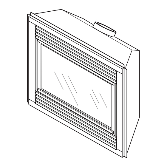
Page 38: Illustrated Parts Breakdown And Parts List
ILLUSTRATED PARTS bREAkDOWN MODELS TC36N, VTC36N, TC36P AND VTC36P SERIES www.desatech.com 116192-01G... -
Page 39: Parts List
MODELS TC36N, VTC36N, TC36P AND VTC36P SERIES This list contains replaceable parts used in your fireplace. When ordering parts, follow the instructions listed under Replacement Parts on page 37 of this manual. pART NUMBER DESCRIpTION Firebox Assembly Face Weldment 108010-01 Door Assembly 108011-01 Top Louver Assembly... - Page 40 ILLUSTRATED PARTS bREAkDOWN BURNER ASSEMBLY FOR MODELS TC36N, VTC36N, TC36P AND VTC36P SERIES www.desatech.com 116192-01G...
- Page 41 BURNER ASSEMBLY FOR MODELS TC36N, VTC36N, TC36P AND VTC36P SERIES This list contains replaceable parts used in your fireplace. When ordering parts, follow the instructions listed under Replacement Parts on page 37 of this manual. pART NUMBER 26808 11107 11102 116344-01 Tubing Assembly 111288-02 Flex Gas Line 108084-02 Pilot Assembly (Natural Gas)
-
Page 42: Accessories
Purchase these fireplace accessories from your local retailer. If they can not supply these accessories, call DESA’s Sales Department at 1-866-672-6040. for information. You can also write to the address listed on the back page of this manual. BRICK LINER KIT... - Page 43 ACCESSORIES Continued RECEIvER AND HAND-HELD ON/OFF REMOTE CONTROL KIT - HRC100 SERIES Allows the fireplace to be turned on and off conveniently. A wall-mounted docking station is included. WALL MOUNTED THERMOSTAT CONTROL KIT - GWMT1 (Not Shown) Allows easy wall access for thermostatic operation of your fireplace.
-
Page 44: Limited Warranty
We make no other warranty, expressed or implied. DESA warrants this product to be free from defects in materials and components for two (2) years from the date of first purchase, provided that the product has been properly installed, operated and maintained in accordance with all applicable instructions.
Need help?
Do you have a question about the (V)TC36N(-HA) Series, (V)TC36P(-HA) Series and is the answer not in the manual?
Questions and answers