
Related Manuals for PowerUp UP400

Summary of Contents for PowerUp UP400
- Page 1 User guide PowerUP series generators UP200 I UP400 I UP1K Version 2.0 I 15 September 2022 ENGLISH...
-
Page 2: Table Of Contents
Table of Contents 1. Introduction 1.1 Foreword 1.2 Safety information 1.3 Compliance 1.4 Warranty 2. Product 2.1 Overview 2.2 Front panel Interface 2.2.1 User menu 2.3 Specification 2.4 Box content 3. Installation 3.1 Tools 3.2 Generator installation 3.3 Gas system assembly 3.4 Gas system connection 3.5 Electrical connection 3.5.1 Generator mode... - Page 3 5. Maintenance 5.1 Filters replacement 6. Troubleshooting 6.1 Errors and Troubleshooting 6.2 Recharging the internal battery 6.3 Support contact 7. Transportation and storage 7.1 Transportation requirements 7.2 Storage requirements 8. End of life and disposal...
-
Page 4: Introduction
1. Introduction 1.1 Foreword Thank you for choosing PowerUP Energy Technologies as your clean energy provider! Have fun with your new energy supply system. Please read these installation instructions before using the generator. Kindly contact us if you have any questions about installing or using your generator. -
Page 5: Safety Information
Before operating, read the instructions and keep them for reference. Be sure that you adhere to all manual instructions. WARNING! → The PowerUP series generators may only be operated in a well- ventilated environment. → Ensure that airflow is not obstructed by any objects. - Page 6 → When storing or using hydrogen cylinders indoors, it is recommended to install an external, wall-mounted hydrogen alarm within that space to detect leaks. Please contact PowerUP sales@powerup-tech.com to procure and install such an alarm. → Do not handle compressed hydrogen gas cylinders without training or prior experience.
-
Page 7: Compliance
You may use your receipt, invoice, or other evidence of purchase as a record of the time and date. You should safely store these papers. Our warranty services are based on the current Powerup warranty terms and conditions. Email: support@powerup-tech.com... -
Page 8: Product
POWER IN POWER IN ON/OFF ON/OFF EMERGENCY EMERGENCY POWER IN POWER IN POWER OUT POWER OUT USB-A USB-A POWER OUT POWER OUT CAN BUS CAN BUS USB-A USB-A ON/OFF ON/OFF CAN BUS CAN BUS HYDROGEN HYDROGEN HYDROGEN HYDROGEN UP200, UP400 UP1K... -
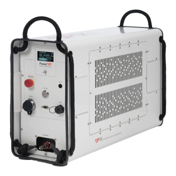
Page 9: User Menu
1. Monochrome display (see detailed description in 2.2.1) 2. Emergency OFF Button 3. Clickable Rotary Encoder Used to navigate through the menu 4. DC In 14V, 6.5mmOD, 4.4mmID 5. DC Out 3-pin, 12V/24V Selectable 6. ON/OFF Button 7. USB Port, Type A 5V, 500mA 8. -
Page 10: Specification
2.3 Specification Parameter/Product UP200 UP400 UP1K Fuel Cell Technology PEM (proton-exchange membrane) Fuel Cell Cooling Type Forced Air Unit Type Stand alone Nominal Power Output, W 1000 Nominal Current, A Nominal Output Voltage, V DC 12 /24 selectable Max Output Voltage, V DC... -
Page 11: Box Content
2.4 Box content (1) UP Generator (UP200/400/1K) (2) DC Output Cable (3) Battery Charger (4) Gas System EMERGENCY POWER IN ON/OFF POWER OUT USB-A CAN BUS HYDROGEN... -
Page 12: Installation
3. Installation 3.1 Tools Generator Installation does not require any tools. Standard gas system assembly requirements: → 2 pieces of 28 mm Wrenches → M2.5 hex screwdriver 3.2 Generator installation → UP series generators require oxygen from air for their operation, therefore generators shall be installed in the spaces with an adequate air flow. -
Page 13: Gas System Assembly
3.3 Gas system assembly Only applicable if the gas system is supplied by PowerUP or its official partners. To connect the regulator to the cylinder, two (2) number 28 wrenches are required. Please follow these instructions. 1. Inspect cylinder(s), regulator, hose and quick connector for any physical damage. -
Page 14: Gas System Connection
3.4 Gas system connection 1. Connect the connector-end of the hydrogen hose on the regulator assembly to the ‘Hydrogen Inlet’ port of the generator. 2. Push the connector onto the ‘Hydrogen Inlet’ port until a loud click is heard, which indicates that an airtight connection has been established. - Page 15 4. The regulator assembly has two gauges – one shows the pressure upstream of the regulator (= inside the cylinder) and the other one downstream of the regulator (= going into the generator). Check that the downstream pressure is between 0.36 and 0.56 barg. If it is not, adjust it by rotating the pin on top of the regulator very slowly.
-
Page 16: Electrical Connection
3.5 Electrical connection 3.5.1 Generator mode 1. Select generator mode in the menu. 2. Check provided cables for damage. 3. Connect open ends of DC output cable to your load. 4. Plug DC output cable directly into the ‘DC Out’ port of the generator. -
Page 17: Battery Charging Mode
3.5.2 Battery Charging Mode 1. Select battery charger mode in the menu. 2. Check provided cables for damage. 3. Connect open ends of DC output cable to your load. 4. Plug DC output cable into the ‘DC Out’ port of the generator. 5. -
Page 18: Operations
4. Operations 4.1 Operating modes Mode Description Initializing After being turned on, the generator checks the condition of all its components, hydrogen supply and internal electrical connection. Warmup The generator preconditions the fuel cell stack to be able to output rated power. Ready The generator is ready. -
Page 19: Switching On
4.2 Switching on 1. To turn on the generator, press ON/OFF. 2. The display and cooling fans will switch on. 3. Wait 30 to 120 s before using the unit. Once the generator is ready, the interface will show “Ready mode.” 4.3 Switching off 1. -
Page 20: Hydrogen Cylinder Refilling
→ A small amount of dirt may lodge in the regulator which might cause it to malfunction. Inspect the regulator thoroughly and clean carefully if necessary! → Smoking near the cylinders is strictly prohibited! → Changing the cylinders near open fire is strictly prohibited! 4.5 Hydrogen cylinder refilling The tank must always be filled by suitably qualified persons who are simultaneously confident that neither the cylinder nor the valve body... -
Page 21: Maintenance
→ Filters must be changed after every 6 months or 2000 hours of operation in dry environments; whichever comes sooner. → Filters must be changed after every 3 months or 1000 hours of operation in wet environments; whichever comes sooner. Please contact PowerUP - support@powerup-tech.com for the procurement of replacement filters. -
Page 22: Troubleshooting
18%. Hydrogen Hydrogen Generator Contact PowerUP Leakage concentration shuts down. regarding the inside the servicing of your generator generator and/ enclosure has or regulator increased to assembly. - Page 23 Insufficient The generator Generator Inspect the H2 Supply is not receiving does not go connection of sufficient into ready the regulator hydrogen fuel. mode. assembly and the ‘Hydrogen Inlet’ port. Check the regulator assembly and pressure on both gauges. ER16 Overcurrent Too much current Generator...
- Page 24 In some cases, error states can occur in combination, as shown in the table below: Error Code Description ER17 Overcurrent + Overheating ER20 Overcurrent + Hydrogen Leakage Oxygen Depletion + Hydrogen Leakage ER48 Low Internal Battery + Overcurrent ER40 Low Internal Battery + Insufficient H2 Supply ER36 Low Internal Battery + Hydrogen...
-
Page 25: Recharging The Internal Battery
‘DC In’ port of the generator. 2. Charge the internal battery for 30 mins. 3. Disconnect the charger, then power on the generator. Only use the proprietary charger you received with the generator. 6.3 Support contact If the issue persists, please contact PowerUP support: support@powerup-tech.com... -
Page 26: Transportation And Storage
7. Transportation and storage 7.1 Transportation requirements → To protect the generator from damage, always transport the generator in its original packaging. → Do not stack generator boxes or place heavy items on top of them. 7.2 Storage requirements → Keep the generator in a cool, dry place. →... -
Page 27: End Of Life And Disposal
8. End of life and disposal Dispose of the packaging in an environmentally responsible way in accordance with the local regulations. To recycle old fuel cell generators, please contact our support line: support@powerup-tech.com... - Page 28 PowerUP Energy Technologies +372 503 6963 Akadeemia tee 23, info@powerup-tech.com 12618 Tallinn, Estonia powerup-tech.com...
Need help?
Do you have a question about the UP400 and is the answer not in the manual?
Questions and answers