Table of Contents
Advertisement
Quick Links
Operating and Installation Instructions
1.0 General information on operating instructions............................................................................................. 2-3
2.0 Notes on possible dangers ............................................................................................................................. 2-3
2.1 Significance of symbols ........................................................................................................................... 2-3
2.2 Explanatory notes on safety information ................................................................................................... 2-4
3.0 Storage and transport ..................................................................................................................................... 2-4
4.0 Description ....................................................................................................................................................... 2-5
4.1 Field of application .................................................................................................................................... 2-5
4.2 Method of functioning................................................................................................................................ 2-5
4.3 Diagram .................................................................................................................................................... 2-6
4.3.3 Parts list ........................................................................................................................................... 2-8
4.4 Technical data ........................................................................................................................................... 2-9
4.5 Interface description................................................................................................................................ 2-12
4.5.1 Control - Run commands .............................................................................................................. 2-12
4.5.2 Feedback ..................................................................................................................................... 2-13
4.5.3 Design notes .................................................................................................................................. 2-14
4.6 Dimensions ............................................................................................................................................. 2-17
0040501006 2422 english (englisch)
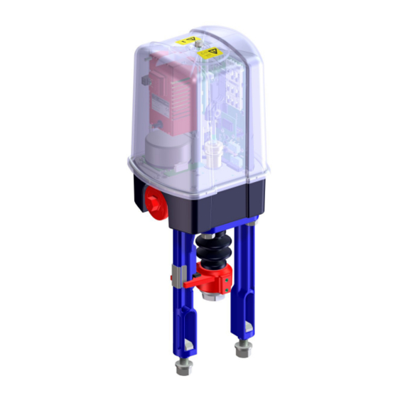
Thrust actuator
ARI-PREMIO
Contents
®
-Plus 2G 2,2 - 5 kN ................................................................................................... 2-6
®
-Plus 2G 12 - 25 kN .................................................................................................. 2-7
®
-Plus 2G
- Translated original instructions -
Advertisement
Table of Contents
Troubleshooting

Related Manuals for ARI ARI-PREMIO-Plus 2G


Summarization of Contents
Notes on Possible Dangers
Significance of Symbols
Explains symbols used for warnings and information.
Explanatory Notes on Safety Information
Provides detailed explanations of safety information and warnings.
Description
Field of Application
Describes the intended uses and applications of the thrust actuator.
Method of Functioning
Explains how the thrust actuator operates and its control mechanisms.
Diagram
Visual representations of the thrust actuator components.
ARI-PREMIO®-Plus 2G 2,2 - 5 kN
Diagram for the 2.2 - 5 kN thrust actuator yoke and column versions.
ARI-PREMIO®-Plus 2G 12 - 25 kN
Diagram for the 12 - 25 kN thrust actuator yoke and column versions.
Parts List
Lists all individual parts of the thrust actuator with their designations.
Technical Data
Detailed technical specifications and parameters of the thrust actuator.
Interface Description
Control - Run Commands
Describes how to control the actuator's operation and run commands.
Feedback
Explains the feedback signals provided by the actuator.
Design Notes
Important design considerations for control signals and fail-safe behavior.
Dimensions
Provides physical dimensions and drawings of the thrust actuator.
Installation
General Installation Data
General guidelines and requirements for a correct installation.
Manual Operation
Instructions for operating the actuator manually.
Mounting to Valves
Steps for physically mounting the actuator onto various valves.
Electrical Connection
Detailed instructions for wiring the thrust actuator.
Wiring Diagram ARI-PREMIO®-Plus 2G 2,2 - 25 kN
Wiring diagram for the 2.2-25 kN models.
Wiring Diagram ARI-PREMIO®-Plus 2G 2,2 - 25 kN dTRON316
Wiring diagram for dTRON316 integrated controller models.
Connection
Specifics on connecting the actuator's electronics and components.
Settings - Handling
Display and Operating Elements of the Standard Electronics
Overview of the display and controls on the actuator's electronics.
LEDs
Explanation of the different LED indicators and their meanings.
Switch Functions
Details on the functions and settings of the slide switches.
Special Functions
ECONOMY-Wear Reduction Program
Explains the program to minimize wear on the actuator and valve.
Temperature Management
Details the function to prevent internal overheating of the actuator.
Condensation on the Printed Circuit Board
Describes the function to prevent condensation on the PCB.
"Y-in" Signal Failure
Explains the actuator's behavior during analogue input signal failure.
Double Control at the 3-Point Input
Describes the effect of simultaneous 3-point and analogue signals.
Priorities
Outlines the priority order for different control signals and states.
Options
Relay Card
Details the relay card for signalling system states and positions.
Analogue Output Card - Yout
Describes the analogue output card for signalling actuator position.
Communications Package
Information on the BT module for wireless communication.
Fieldbus Interface - ANYBUS®-Module
Details on ANYBUS modules for fieldbus communication.
Heating
Instructions for installing the heating resistor to prevent condensation.
Power Supply
Guidance on installing and connecting the power supply unit.
LED-Status Indicator
Instructions for installing the LED status indicator.
Integrated (Process-) Controller dTRON 316
Information on the integrated JUMO dTRON 316 process controller.
Putting the Actuator into Operation
Configuring the Control Signal
How to set up the control signal before initialization.
Connecting the Supply Voltage
Instructions for connecting the actuator's power supply.
Initialization
Procedure for initializing the actuator to determine valve stroke and control type.
Troubleshooting
Troubleshooting Table
A table listing faults, possible causes, and remedies.
Failure Signals According to NAMUR NE 107
Explains failure signals based on NAMUR NE 107 standards.
LED-Encoding (from Software Version 2.1.7 and Higher)
Describes the meaning of LED combinations for status and errors.
Need help?
Do you have a question about the ARI-PREMIO-Plus 2G and is the answer not in the manual?
Questions and answers