Table of Contents
Advertisement
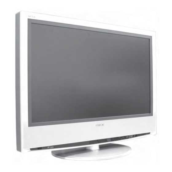
SERVICE MANUAL
MODEL
KLV-S23A10E
KLV-S26A10E
KLV-S32A10E
RM-EA002
COMMANDER
DEST
RM-EA002
AEP
RM-EA002
AEP
RM-EA002
AEP
KLV-S23A10E / KLV-S26A10E / KLV-S32A10E
KDL-S23A12U / KDL-S26A12U / KDL-S32A12U
- 1 -
WAX
MODEL
KDL-S23A12U
KDL-S26A12U
KDL-S32A12U
FLAT PANEL COLOR TV
WAX
RM-EA002 / RM-ED002
CHASSIS
COMMANDER
DEST
RM-ED002
UK
RM-ED002
UK
RM-ED002
UK
RM-ED002
Advertisement
Table of Contents

Related Manuals for Sony KLV-S32A10E


Summarization of Contents
SERVICE MANUAL WAX CHASSIS
Model and Chassis Information
Lists the models covered by the service manual and their respective chassis.
Self Diagnosis Support
Information regarding the self-diagnosis feature supported by the chassis.
General Information and Setup
Cautions and Specifications
General cautions and technical specifications for the TV models.
Connectors and Self Diagnosis
Details on TV connectors and the self-diagnosis function.
Disassembly Procedures
Step-by-Step Disassembly
Detailed instructions for disassembling various TV components.
Set-up Adjustments
Signal and White Balance Adjustments
Procedures for adjusting signal input and white balance.
Test Mode Operations
Instructions for using the service test mode for adjustments.
Diagrams and Schematics
Block Diagrams
High-level block diagrams illustrating the TV's architecture.
Schematic Diagrams and PWBs
Detailed circuit schematics and printed wiring board layouts.
Circuit Board Locations
Diagrams showing the physical location of circuit boards within the TV.
Exploded Views
Chassis Exploded View
Exploded view of the TV chassis with part references.
Rear Cover and Stand Exploded View
Exploded view of the rear cover and stand with part references.
Cautions and Service Notes
Lead Free Solder Boards Caution
Specific precautions for servicing boards using lead-free solder.
Product Specifications
Model and System Specifications
Details on TV models, systems, channel coverage, and color systems.
General Specifications
Information on power, dimensions, and weight of the TV.
Input/Output Terminals
Description of all available input and output connections.
Supplied Accessories and Features
List of included accessories and key TV features.
Model-Specific Warnings
UK Model Mains Lead Warning
Safety warning specific to UK models regarding the mains lead and plug.
Connector Pinout Details
21-pin Connector Signals
Detailed pinout and signal level information for the 21-pin connector.
Rear and Side Panel Connections
Overview of connections available on the rear and side panels.
S-Video Socket Pin Configuration
Pinout details for the S-Video socket.
Self-Diagnostic Software
LED Error Code Descriptions
List of LED error codes and their corresponding error descriptions.
General Operation and Setup
Connecting Aerial and VCR
Instructions for connecting external aerial and VCR equipment.
Preventing TV Toppling
Guidance on securing the TV to prevent it from toppling.
Initial TV Power On
Steps for the first-time power-on and initial setup.
TV Tuning and Viewing
Auto-tuning the TV
Procedure for automatically tuning all available channels.
Watching TV Controls
How to switch modes, select channels, and use additional watching features.
Digital Features Navigation
Digital Electronic Programme Guide (EPG)
How to check and use the Digital Electronic Programme Guide.
Viewing Connected Equipment
Instructions for viewing content from connected equipment.
Navigating Menus
Guide on navigating through the TV's menu system.
Picture Adjustment Menu
Picture Mode and Colour Tone
Adjusting picture modes (Vivid, Standard, Custom) and colour tone.
Brightness, Contrast, Sharpness
Adjusting picture settings like brightness, contrast, hue, and sharpness.
Sound Adjustment Menu
Sound Effect and Treble/Bass/Balance
Selecting sound effects and adjusting audio levels (treble, bass, balance).
Reset Sound Settings
Restoring sound settings to factory defaults.
Screen and Feature Settings
Screen Format Options
Adjusting screen aspect ratio (Wide, Smart, 4:3, etc.).
RGB Center Adjustment
Adjusting the horizontal picture position for RGB input.
Power Saving and Light Sensor
Configuring power saving modes and light sensor function.
AV2 Output Settings
Configuring the AV2 output signal for recording or other devices.
Timer and Setup Functions
Timer Settings
Setting sleep timers, clock, and on/off timers.
Set Up Menu Options
Accessing and using the Set Up menu for tuning and sorting.
Connecting Optional Equipment
Side TV Connections
Connecting external devices to the side panel of the TV.
Rear TV Connections
Connecting external devices to the rear panel of the TV.
Detailed Product Specifications
Display Unit and Panel Specifications
Detailed specs for screen size, resolution, power, dimensions, and weight.
Colour System and Terminals
Information on color systems, aerial input, and terminal types.
Sound Output and PC Specifications
Details on sound output power and PC input specifications.
Supplied Accessories and Optional Accessories
List of included accessories and available optional accessories.
Troubleshooting Guide
Picture Issues and Remedies
Common picture problems and their troubleshooting steps.
Sound Issues and Remedies
Troubleshooting steps for common sound problems.
Channel and General Issues
Troubleshooting channel selection and general TV operational issues.
Section 2: Disassembly
2-1. Stand Removal
Instructions for removing the TV stand.
2-2. Rear Cover Removal
Procedure for removing the rear cover of the TV.
Disassembly Procedures
2-3. Shield Cover Removal
Instructions for removing the shield cover.
2-4. Display Cover Removal
Procedure for removing the display cover.
Disassembly Procedures
2-5. Speaker Removal
Instructions for removing the speakers.
2-6. A2E Board Removal
Procedure for removing the A2E circuit board.
Disassembly Procedures
2-7. BE Board Removal
Procedure for removing the BE circuit board.
2-8. G2 Board Removal
Procedure for removing the G2 circuit board.
Disassembly Procedures
2-9. GE2 Board Removal
Procedure for removing the GE2 circuit board.
2-10. H1E Board Removal
Procedure for removing the H1E circuit board.
Disassembly Procedures
2-11. H2 Board Removal
Procedure for removing the H2 circuit board.
2-12. H3 Board Removal
Procedure for removing the H3 circuit board.
Disassembly Procedures
2-13. N Board Removal
Procedure for removing the N circuit board.
2-14. N1 Board Removal
Procedure for removing the N1 circuit board.
Section 3: Set-up Adjustments
How to Enter Service Mode
Steps to access the service mode using the remote commander.
3-1. Signal Adjustment Procedures
Instructions for PAL and SECAM auto signal adjustments.
3-2. White Balance Adjustment Procedures
Procedures for white balance adjustment (H/L, C/O, Secam).
White Balance Adjustment Details
3-2.2. White Balance Adjustment (C/O)
Cut Off adjustments for white balance (PAL CVBS, SECAM CVBS).
3-2.3. SECAM White Balance Adjustment (H/L)
Drive adjustments for SECAM white balance (60 IRE).
Set-up Adjustments and Test Modes
3-2.4. SECAM White Balance Adjustment (C/O)
Cut Off adjustments for SECAM white balance (20 IRE).
3-3. TEST TEST MODE Functions
List of functions available in the service test mode.
Block Diagrams
Block Diagram 1 (Main Processor & I/O)
Block diagram showing main microprocessor, serial EEPROM, and I/O connections.
Block Diagrams
Block Diagram 2 (LSI Controller & MPEG2 Decoder)
Block diagram illustrating LSI controller, flash memory, and MPEG2 decoder.
Block Diagrams
Block Diagram 3 (Power Supplies)
Block diagrams for G1 and GE1 power supply units.
Block Diagrams
Block Diagram 4 (A2E Analog Tuner & Chroma)
Block diagram of A2E board: analog tuner, audio amp, chroma decoder.
Block Diagrams
Block Diagram 5 (A2E AV Switch & YUV)
Block diagram of A2E board: AV switch, SCARTs, YUV input.
Block Diagrams
Block Diagram 6 (A2E HDMI & Audio)
Block diagram of A2E board: HDMI interface, audio outputs, and power amplifiers.
Block Diagrams
Block Diagram 7 (A2E Analog Tuner Details)
Detailed block diagram of the A2E board's analog tuner section.
Diagrams and Component Locations
Block Diagram 8 (Power Supplies)
Block diagrams for G2 and GE2 power supply units.
Circuit Board Locations
Diagrams indicating the physical location of all major circuit boards.
Schematic Diagrams and PWBs
References to schematic diagrams and printed wiring board layouts.
A2E Board Schematic Diagram
A2E Schematic Diagram - Page 1/5
Schematic for A2E board: tuner, audio amp, chroma decoder, AV switch, SCARTs, YUV input.
A2E Board Schematic Diagram
A2E Schematic Diagram - Page 2/5
Schematic for A2E board: audio processor, AV switch, and headphone circuits.
A2E Board Schematic Diagram
A2E Schematic Diagram - Page 3/5
Schematic for A2E board: chroma decoder, sync separator, and RGB switch circuits.
A2E Board Schematic Diagram
A2E Schematic Diagram - Page 4/5
Schematic for A2E board: SCART inputs, HDMI, and audio output circuits.
A2E Board Schematic Diagram
A2E Schematic Diagram - Page 5/5
Schematic for A2E board: power supply regulators and control signals.
A2E Board Component Information
Printed Wiring Board Layout (Side A)
Layout of the A2E board's printed wiring on the conductor side A.
IC Voltage and Location Tables (Side A)
Voltage and location data for ICs on the A2E board (Side A).
A2E Board Component Information
Printed Wiring Board Layout (Side B)
Layout of the A2E board's printed wiring on the conductor side B.
Semiconductor Location Table (Side B)
Location data for semiconductors on the A2E board (Side B).
A2E Board Variant Parts
Variant Parts Table
Table detailing component differences for variant models.
BE Board Schematic Diagram
BE Schematic Diagram [ Video Processor, PC Input ]
Schematic for BE board: video processor and PC input circuitry (Page 1/6).
BE Board Schematic Diagram
BE Schematic Diagram [ Video Processor, PC Input ]
Schematic for BE board: video processor and PC input circuitry (Page 2/6).
BE Board Schematic Diagram
BE Schematic Diagram [ Video Processor, PC Input ]
Schematic for BE board: video processor and PC input circuitry (Page 3/6).
BE Board Schematic Diagram
BE Schematic Diagram [ Video Processor, PC Input ]
Schematic for BE board: video processor and PC input circuitry (Page 4/6).
BE Board Schematic Diagram
BE Schematic Diagram [ Video Processor, PC Input ]
Schematic for BE board: video processor and PC input circuitry (Page 5/6).
BE Board Schematic Diagram
BE Schematic Diagram [ Video Processor, PC Input ]
Schematic for BE board: video processor and PC input circuitry (Page 6/6).
BE Board Component Information
Printed Wiring Board Layouts (Side A & B)
Layouts of the BE board's printed wiring on both conductor sides.
Semiconductor Location Tables (Side A & B)
Location data for semiconductors on the BE board (Sides A & B).
G1 Board Schematic Diagram
G1 Board Schematic Diagram [ Power Supply ]
Schematic diagram of the G1 board's power supply unit.
G1 Board Component Information
Printed Wiring Board Layouts (Side A & B)
Layouts of the G1 board's printed wiring on both conductor sides.
Semiconductor Location Tables (Side A & B)
Location data for semiconductors on the G1 board (Sides A & B).
GE1 Board Schematic Diagram
GE1 Board Schematic Diagram [ Power Supply Regulator ]
Schematic diagram of the GE1 board's power supply regulator.
GE1 Board Component Information
Printed Wiring Board Layouts (Side A & B)
Layouts of the GE1 board's printed wiring on both conductor sides.
Semiconductor Location Tables (Side A & B)
Location data for semiconductors on the GE1 board (Sides A & B).
G2 Board Schematic Diagram
G2 Board Schematic Diagram [ Power Supply ]
Schematic diagram of the G2 board's power supply unit.
G2 Board Component Information
Printed Wiring Board Layout (Side A)
Layout of the G2 board's printed wiring on the conductor side A.
Semiconductor Location Table (Side A)
Location data for semiconductors on the G2 board (Side A).
G2 Board Component Information
Printed Wiring Board Layout (Side B)
Layout of the G2 board's printed wiring on the conductor side B.
Semiconductor Location Table (Side B)
Location data for semiconductors on the G2 board (Side B).
GE2 Board Schematic Diagram
GE2 Board Schematic Diagram [ Power Supply Regulator ]
Schematic diagram of the GE2 board's power supply regulator.
GE2 Board Component Information
Printed Wiring Board Layouts (Side A & B)
Layouts of the GE2 board's printed wiring on both conductor sides.
Semiconductor Location Tables (Side A & B)
Location data for semiconductors on the GE2 board (Sides A & B).
IC and Semiconductor Voltage Tables
Voltage information for ICs and semiconductors on the GE2 board.
N Board Schematic Diagram
N Board Schematic Diagram [ MPEG2 Decoder ]
Schematic for N board: MPEG2 decoder circuitry (Page 1/7).
N Board Schematic Diagram
N Board Schematic Diagram [ MPEG2 Decoder ]
Schematic for N board: MPEG2 decoder circuitry (Page 2/7).
N Board Schematic Diagram
N Board Schematic Diagram [ MPEG2 Decoder ]
Schematic for N board: MPEG2 decoder circuitry (Page 3/7).
N Board Schematic Diagram
N Board Schematic Diagram [ MPEG2 Decoder ]
Schematic for N board: MPEG2 decoder circuitry (Page 4/7).
N Board Schematic Diagram
N Board Schematic Diagram [ MPEG2 Decoder ]
Schematic for N board: MPEG2 decoder circuitry (Page 5/7).
N Board Schematic Diagram
N Board Schematic Diagram [ MPEG2 Decoder ]
Schematic for N board: MPEG2 decoder circuitry (Page 6/7).
N Board Schematic Diagram
N Board Schematic Diagram [ MPEG2 Decoder ]
Schematic for N board: MPEG2 decoder circuitry (Page 7/7).
N Board Component Information
Printed Wiring Board Layouts (Side A & B)
Layouts of the N board's printed wiring on both conductor sides.
Semiconductor Location Tables (Side A & B)
Location data for semiconductors on the N board (Sides A & B).
Board Schematic Diagrams
H1E Board Schematic Diagram (Switches)
Schematic for H1E board showing switch circuits.
H2 Board Schematic Diagram (Y/C, AV, Headphones)
Schematic for H2 board covering Y/C, AV, and headphone circuits.
H3 Board Schematic Diagram (Sircs, Leds, Light Sensor)
Schematic for H3 board covering SIRCS, LEDs, and light sensor.
Board Printed Wiring Board Layouts
H1E Board Layouts (Side A & B)
Layouts of the H1E board's printed wiring on both conductor sides.
H2 Board Layouts (Side A & B)
Layouts of the H2 board's printed wiring on both conductor sides.
H3 Board Layouts (Side A & B)
Layouts of the H3 board's printed wiring on both conductor sides.
N1 Board Schematic Diagram
N1 Board Schematic Diagram [ RF Splitter and Digital Tuner ]
Schematic for N1 board: RF splitter and digital tuner.
N1 Board Component Information
Printed Wiring Board Layouts (Side A & B)
Layouts of the N1 board's printed wiring on both conductor sides.
Semiconductor Location Tables (Side A & B)
Location data for semiconductors on the N1 board (Sides A & B).
Semiconductors
Semiconductor Types and Images
List of semiconductor components with their images and reference numbers.
Section 5: Exploded Views
5-1. Chassis Exploded View
Exploded view of the chassis assembly with parts list and screw types.
Exploded Views - Chassis Continued
5-1. Chassis Exploded View Parts List
Detailed parts list for the chassis exploded view.
Exploded Views - Rear Cover and Stand
5-2. Rear Cover and Stand Exploded View
Exploded view of the rear cover and stand with parts list and screw types.
Section 6: Electrical Parts List
Parts Listing Table of Contents
Table of contents for the electrical parts list sections.
Board Specific Parts Lists
Index of parts lists organized by circuit board.
Electrical Parts List - Board Specifics
H2, H3, and A2E Board Parts Lists
Complete parts lists for H2, H3, and A2E circuit boards.
G2 Board Complete Parts List
Complete parts list for the G2 circuit board.
Electrical Parts List - Board Specifics
N1 Board Complete Parts List
Complete parts list for the N1 circuit board (Digital Models only).
BE Board Complete Parts List
Complete parts list for the BE circuit board.
A2E Board Common Parts List
List of common parts used on the A2E board.
Electrical Parts List - Common Parts
A2E Board Common Parts List (Capacitors)
List of capacitors used on the A2E board.
Electrical Parts List - Common Parts
A2E Board Common Parts List (Capacitors)
List of capacitors used on the A2E board.
Electrical Parts List - Common Parts
A2E Board Common Parts List (Resistors, Connectors, Diodes, ICs)
List of resistors, connectors, diodes, and ICs on the A2E board.
Electrical Parts List - Common Parts
A2E Board Common Parts List (Resistors, Transistors)
List of resistors and transistors used on the A2E board.
Electrical Parts List - Common Parts
A2E Board Common Parts List (Resistors)
List of resistors used on the A2E board.
Electrical Parts List - Common Parts
A2E Board Common Parts List (Resistors)
List of resistors used on the A2E board.
Electrical Parts List - Common Parts
A2E Board Common Parts List (Resistors)
List of resistors used on the A2E board.
Electrical Parts List - Common Parts
A2E Board Common Parts List (Resistors)
List of resistors used on the A2E board.
Electrical Parts List - Common Parts
A2E Board Common Parts List (Resistors)
List of resistors used on the A2E board.
Electrical Parts List - Common Parts
A2E Board Common Parts List (Resistors)
List of resistors used on the A2E board.
A2E Board Common Parts List (Varistors)
List of varistors used on the A2E board.
Electrical Parts List - KDL-S23A12U Specifics
KDL-S23A12U Resistors, Tuner, Varistors
Specific components for KDL-S23A12U: resistors, tuner, varistors.
KDL-S23A12U Capacitors
Specific capacitors for the KDL-S23A12U model.
Electrical Parts List - KLV-S26A10E/KLV-S32A10E Specifics
KLV-S26A10E/KLV-S32A10E Parts List
Complete parts list for KLV-S26A10E and KLV-S32A10E models.
Electrical Parts List - KDL-S26A12U/KDL-S32A12U Specifics
KDL-S26A12U/KDL-S32A12U Parts List
Complete parts list for KDL-S26A12U and KDL-S32A12U models.
Electrical Parts List - KDL-S26A12U/KDL-S32A12U Specifics
KDL-S26A12U/KDL-S32A12U Parts List
Complete parts list for KDL-S26A12U and KDL-S32A12U models.
Electrical Parts List - Board Specifics
GE2 Board Complete Parts List
Complete parts list for the GE2 circuit board.
H1E Board Complete Parts List
Complete parts list for the H1E circuit board.
G1 Board Complete Parts List
Complete parts list for the G1 circuit board.
Electrical Parts List - Board Specifics
G1 Board Complete Parts List
Parts list for G1 board: capacitors, connectors, diodes, fuses, ICs, coils, etc.
Electrical Parts List - Board Specifics
G1 Board Complete Parts List
Resistor list for the G1 board.
Electrical Parts List - Board Specifics
N Board Complete Parts List
Complete parts list for the N circuit board (Digital Models only).
N1 Board Complete Parts List
Complete parts list for the N1 circuit board (Digital Models only).
BE Board Complete Parts List
Complete parts list for the BE circuit board.
Electrical Parts List - Board Specifics
BE Board Complete Parts List
Parts list for BE board: resistors, connectors, diodes.
Electrical Parts List - Board Specifics
BE Board Complete Parts List
Capacitor list for the BE circuit board.
Electrical Parts List - Board Specifics
BE Board Complete Parts List
Parts list for BE board: diodes, fuses, ferrite beads, ICs, coils, etc.
Electrical Parts List - Board Specifics
BE Board Complete Parts List
Resistor list for the BE circuit board.
Electrical Parts List - Board Specifics
BE Board Complete Parts List
Resistor list for the BE circuit board.
Electrical Parts List - Board Specifics
BE Board Complete Parts List
Resistor list for the BE circuit board.
Electrical Parts List - Board Specifics
BE Board Complete Parts List
Resistor list for the BE circuit board.
Electrical Parts List - Board Specifics
BE Board Complete Parts List
Capacitor list for the BE circuit board.
Electrical Parts List - Board Specifics
BE Board Complete Parts List
Capacitor list for the BE circuit board.
Electrical Parts List - Board Specifics
BE Board Complete Parts List
Ferrite beads, ICs, coils, photo-couplers, transistors, resistors for BE board.
Electrical Parts List - Board Specifics
N Board Complete Parts List
Parts list for N board: ICs, coils, transistors, resistors.
Electrical Parts List - Board Specifics
N Board Complete Parts List
Resistor list for the N board.
Electrical Parts List - Board Specifics
N Board Complete Parts List
Resistor list for the N board.
Electrical Parts List - Board Specifics
N Board Complete Parts List
Resistor list for the N board.
Electrical Parts List - Board Specifics
GE2 Board Complete Parts List
Diodes, fuses, ferrite beads, ICs, coils, transistors for GE2 board.
Electrical Parts List - Board Specifics
GE2 Board Complete Parts List
Capacitors and connectors for the GE2 board.
Electrical Parts List - Board Specifics
G1 Board Complete Parts List
Connectors, diodes, fuses, ferrite beads, ICs, coils, photo-couplers, transistors for G1 board.
Electrical Parts List - Board Specifics
G1 Board Complete Parts List
Resistor list for the G1 board.
Electrical Parts List - Board Specifics
G1 Board Complete Parts List
Resistors, varistors, and crystal for the G1 board.
N Board Complete Parts List
Capacitors, connectors, diodes, fuses, ferrite beads, ICs for N board.
Electrical Parts List - Board Specifics
N Board Complete Parts List
Coils, transistors, and resistors for the N board.
Miscellaneous Items
LCD Panel and Speakers
Parts list for LCD panel and speakers.
Tuner and AC Inlet Filter
Parts list for the tuner and AC inlet filter.
Power Supply Cord Set
Parts list for power supply cord sets.
Accessories and Packaging Materials
List of accessories and packaging materials.
Remote Commander
Parts list for the remote commander units.
Need help?
Do you have a question about the KLV-S32A10E and is the answer not in the manual?
Questions and answers