
Related Manuals for Infinera TM-3000

Summarization of Contents
Introduction to TM-3000
Document Revision History
Details changes and updates across various revisions of the TM-3000 documentation.
Functional Description of TM-3000
Basic Configuration Overview
Explains the standard TM-3000 chassis configuration and included components for a Network Element.
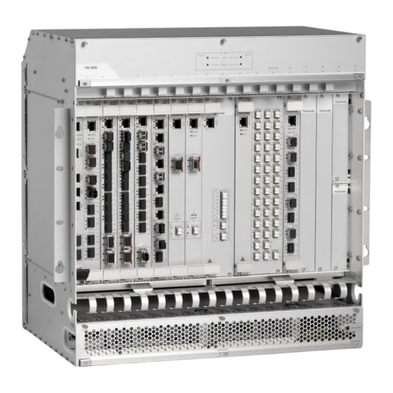
TM-3000 Chassis Structure
Details the physical layout of the TM-3000 chassis, dividing it into fan, card cage, and interface areas.
Rack Mount Options
Covers mounting configurations for 19", ETSI, and 23" racks, including bracket adjustments.
Fan Unit Details
Describes the dual fan units, their function, replacement, and variations across chassis revisions.
Air Filter System
Explains the location, purpose, and maintenance of the air filter for cooling and dust prevention.
Power Supply Options
Details DC-power connectivity and AC/DC converter options for powering the TM-3000 chassis.
External Interfaces and LAN Module
Describes the LAN module, its RJ-45 connectors, and their applications for network connectivity.
Card Cage Slot Configuration
Details the TM-3000 card cage, slot types (CU, active, passive), and shelf extension capabilities.
Chassis Identity and System Mode
Explains setting the chassis subrack ID using DIP switches and the system mode for CU configuration.
Fiber Management Features
Covers fiber management solutions for patch cord routing to ease installation and maintain airflow.
Board Handling and Extraction
Details the board extraction handle and process for safe removal and insertion of plug-in units.
External Alarm Connections
Describes how to connect external alarms using dry contacts or voltage triggers via a break-out box.
Configuration Guidelines
DC-Filters and Power Consumption
Guidelines on DC-filters, card cage power limits, and impact on chassis configurations.
AC/DC Converter Compatibility
Matching AC/DC converter models with specific DC-filter capabilities for power delivery.
High Power Unit Fan Requirements
Specifies required fan units for high-density and high-power traffic units to ensure adequate cooling.
Chassis Power Consumption
Details power consumption for R1-R3 and R4-R5 chassis revisions with different fan and DC-filter units.
Card Cage Slot Usage Rules
Defines slot categories (CU, active, passive) and usage restrictions for plug-in units in the card cage.
Supported Plug-in Units
Lists all plug-in units supported by release R31.0 and their slot and chassis compatibility.
Control Unit (CU) Compatibility
Clarifies compatibility between different Control Unit versions and supported hardware/software objects.
Chassis Revision Updates
R1C Revision Updates
Introduced enhancements for primary power cable and optical patch cord connections.
R2 Revision Updates
Details passing NEBS testing for the US market with minor mechanical changes.
R3 Revision Updates
Introduced a new mechanical solution for the supporting shelf for half-height units.
R4 Revision Updates
Features fiber management solutions, new air filters, and improved fan compartment openings.
Release R15 Updates
Enabled remote inventory of DC/DC-module and chassis via ENM update.
R5 Revision Updates
Introduced a second source for the TM-3000 chassis with minor visual appearance differences.
Board Extraction Tool Enhancements
Details the introduction of a special board extractor for easier full-sized board removal.
Technical Data Specifications
Environmental Conditions
Specifies operating and climate parameters according to ETSI EN 300 019-1-3 standards.
Mechanical Dimensions and Mounting
Provides detailed mechanical dimensions, mounting depths, and chassis height specifications.
Revision History Data
Lists revision data for the M3000/ENC and associated components across different releases.
Ordering Data and Spare Parts
Information on TM-3000 ordering, AC/DC converters, and available spare parts for different revisions.
Appendix: Example Configurations
40x 10GbE System Configuration Example
Example configuration for 40x 10Gb/s channels using TPMRHEX-L/16G Transponders and MDU.
80x 10Gb/s System Configuration Example
Example of an 80x 10Gb/s configuration across two chassis with transponders and MDU units.
Need help?
Do you have a question about the TM-3000 and is the answer not in the manual?
Questions and answers