Table of Contents
Advertisement
Quick Links
HISTORY INFORMATION FOR THE FOLLOWING MANUAL:
REPAIR MANUAL
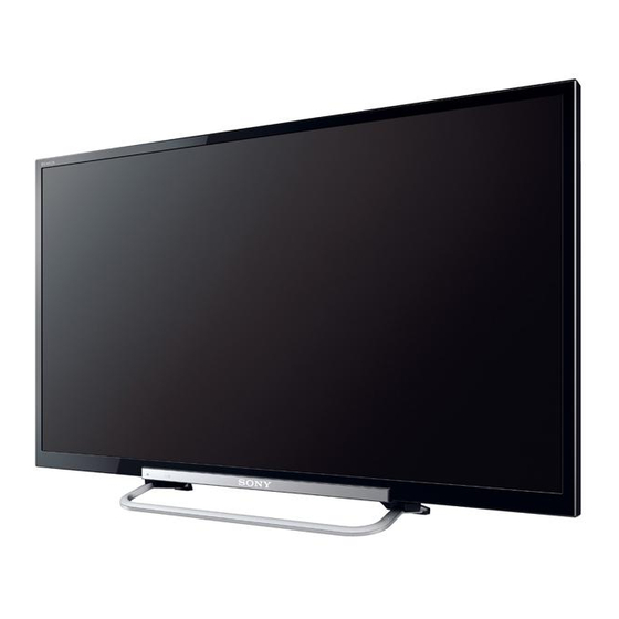
KDL-39R475A
Version
Date
1.0
03/28/2013
Subject
Original Manual Release Date.
RB1TK
MODEL
COMMANDER
KDL-39R475A
RM-YD093
KDL-42R474A
RM-YD093
KDL-42R475A
RM-YD093
KDL-46R475A
RM-YD093
Self Diagnosis
Supported model
Chassis
Segment: BA
DESTINATION
BRAZIL
BRAZIL
BRAZIL
BRAZIL
LCD Digital Color TV
9-883-509-02
Advertisement
Table of Contents

Related Manuals for Sony KDL-42R474A


Summarization of Contents
CAUTIONS AND WARNINGS
CAUTION!!
Servicing instructions for qualified personnel only. Avoid electric shock.
WARNING!!
Use an isolation transformer to avoid shock hazard in case of live chassis.
SAFETY-RELATED COMPONENT WARNING!!
Critical components identified by shading/mark must be replaced with specified part numbers.
ATTENTION!!
Component level repair of Power Supply/Inverter Boards is prohibited for safety.
SAFETY CHECK-OUT
Perform safety checks after service, including connections, wiring, parts, cords, and exposed metal parts.
LEAKAGE TEST
AC leakage to earth ground must not exceed 0.5 mA. Measure using specific methods and equipment.
SECTION 1 - SPECIFICATIONS AND LAYOUTS
SPECIFICATIONS
Details TV system, channel coverage, panel, speakers, inputs/outputs, and model-specific specs.
BOARD LAYOUT
Illustrates the placement of main boards, power supply, TCON, and control keys for different models.
WIRE DRESSING
Shows the routing and arrangement of internal wiring for different TV models.
SECTION 2 - TROUBLESHOOTING
DIAGNOSING THE ERROR
Steps to verify symptoms, check software, and determine the required replacement part.
VIEWING THE SELF CHECK DIAGNOSIS HISTORY
How to access and interpret the TV's self-check error logs.
TRIAGE CHART
A chart to help identify potential causes of errors based on symptoms.
FLOWCHARTS AND DIAGRAMS
Overview of system block diagrams and troubleshooting flowcharts.
POWER AND CONTROL BLOCK DIAGRAM
Detailed block diagram showing power supply and main board connections.
SECTION 3 - REPAIR INFORMATION
REPAIRING THE TV
General steps for repairing the TV, including software updates and verification.
REMOVING THE TABLE-TOP STAND
Instructions and caution for safely removing the TV's table-top stand.
REMOVING THE REAR COVER
Procedure for removing the TV's rear cover and AC cover.
REPLACING THE MAIN BOARD
Step-by-step guide for replacing the main board, including software update.
SERVICE MODE PROCEDURES
Guide to accessing service mode, selecting panel codes, and editing serial numbers.
REPLACING THE POWER SUPPLY BOARD
Instructions for removing, replacing, and updating software for the power supply board.
REMOVING THE SPEAKERS
Procedure for removing the TV speakers, including bezel and screw removal.
REMOVING H BOARD
Steps to disconnect and release the H Board using bezel clips.
SECTION 4 - EXPLODED VIEW/PART NUMBER INFORMATION
TABLE-TOP STAND
Exploded view and part numbers for the table-top stand components.
SCREWS
List of screws used in different models, with part numbers and locations.
CONNECTORS
Part numbers and descriptions for various connector assemblies used in the TVs.
SECTION 5 - ACCESORIES/PART NUMBER INFORMATION
ACCESSORIES AND PACKAGING
Details on standard accessories, packaging, and important notes on screw usage.
OPTIONAL ACCESSORIES
Information on optional accessories available for the TV, such as support belts.
REMOTE COMMANDER
Part number for the remote commander (RM-YD093).
MISCELLANEOUS
Includes labels and shields specific to different TV models.
APPENDIX A: ENCRYPTION KEY COMPONENTS
ENCRYPTION KEY COMPONENTS HANDLING
Guidelines for handling, repair, and disposal of circuit boards with encryption key components.
Need help?
Do you have a question about the KDL-42R474A and is the answer not in the manual?
Questions and answers