Table of Contents
Advertisement
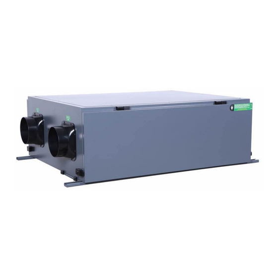
LUKO's FD-S & FD-X Series
DUCTED DEHUMIDIFIER
User's Manual
KEEP THESE INSTRUCTIONS FOR FUTURE REFERENCE
Thank you for choosing our dehumidifier. This owner's manual will provide you with
valuable information necessary for the proper care and maintenance of your new
dehumidifier. Please take a few moments to read the instructions thoroughly and
familiarize with all the operational aspects of this dehumidifier. This unit removes
excessive moisture from the air to create a more comfortable environment.
Advertisement
Table of Contents

Related Manuals for LUKO FD-S140L


Summary of Contents for LUKO FD-S140L
- Page 1 LUKO’s FD-S & FD-X Series DUCTED DEHUMIDIFIER User’s Manual KEEP THESE INSTRUCTIONS FOR FUTURE REFERENCE Thank you for choosing our dehumidifier. This owner’s manual will provide you with valuable information necessary for the proper care and maintenance of your new dehumidifier.
-
Page 2: Table Of Contents
Table of Contents Foreword ........................4 Purpose................................. 4 Content................................. 4 Rights Reserved.............................4 1 SAFETY INTRODUCTION ....................5 1.1 Safety...............................5 1.2 Applications:............................5 1.3 Manual Content............................5 2 INTRODUCTIONS OF DEVICE ..................6 2.1 Standards..............................6 2.2 Structure..............................6 2.2.1 Housing and body........................6 2.2.2 Inlet / Outlet Air Panel.........................6 2.2.3 Refrigeration system........................6 2.2.4 Compressor..........................6... - Page 3 4 OPERATIONS ......................18 Controller Terminals:........................18 Controller Interface:........................19 Parameters Setting.........................19 Symbols Description:........................21 Mode / Function..........................22 Parameters Code / Function......................24 Working Status Display........................25 Error Code............................25 Error Code Address........................25 Safety Cautions..........................26 4.10 5 MAINTENANCES ......................27 5.1 Maintenance introduction........................27 5.2 Filter..............................
-
Page 4: Foreword
Foreword Purpose This manual provides all the information about this precise dehumidifier, including the structure, installation, principle, work process and the detailed operating instruction is provided. Content Dehumidifying control system, operating ways, maintain, and regular failure and failure elimination Rights Reserved We reserve the rights of updating/explaining all contents of manual involved. -
Page 5: Safety Introduction
1 SAFETY INTRODUCTION 1.1 Safety This series of dehumidifier is in conformance with all provisions of European security requirements and standards, the safety of worker and equipment are taken into care while in design and manufacture process. In each section of the manual, there are safety information and explicitly pointed out operation that may causes danger. -
Page 6: Introductions Of Device
2 INTRODUCTIONS OF DEVICE 2.1 Standards The design meets IEC protection class IP 45 requirements. 2.2 Structure 2.2.1 Housing and body Adopts steel frame structure, compact, strong, robust, and the defrosting technology effectively preventing the "frozen" issue; Easy to open / access panel for replacing filter ... -
Page 7: Protection Devices
Fans operation mode: The fan will run and stop according to the RH setpoint. High temperature protection: Prevent the compressor running continuously at high temperatures; Low pressure protection: Prevents the dehumidifier running without refrigerant to avoid compressor from being overload. 2.2.7 Product Diagram FD-S Series Page 7 of 35... - Page 8 FD-X Series Page 8 of 35...
-
Page 9: Installations
3 INSTALLATIONS 3.1 Brief introduction Ceiling Mounted dehumidifier can be installed in many places, depending on the requirements of owners. It can also integrate with current ventilation system via duct system. This chapter records info about preparation work, and installation work and etc. Please serve it as a guide before installation. -
Page 10: Ground/Base
3.6 Ground/Base Dehumidifier must be installed horizontally with well-balanced level. Please use horizontal ruler to measure the level during installation. 3.7 Ducting Connection The dimension of ducting for inlet and outlet air should be in line with ISO7807 recommended values. Ducting should be connected with the connection part on flange, meanwhile, the screw bolt is limited to within 20mm. -
Page 11: Ducting Connection Diagram (Example)
3.8 Ducting Connection Diagram (example) 3.9 Service Access Space Allocation Please allocate the space require as per the table for access to service the unit. Page 11 of 35... -
Page 12: Drainpipe Connection
Service Area Void Area / No Blockage Model FD-S28L / X28L 400mm 490mm 100mm 100mm FD-S40L / X40L 500mm 600mm 100mm 100mm FD-S60L / X60L 500mm 600mm 100mm 100mm FD-S100L / X100L 600mm 650mm 100mm 100mm FD-S140L / X140L 600mm 650mm 100mm 100mm... -
Page 13: Electrical Connection
It is strongly advised to install a U-Trap with PVC pipe or any other pipe that are suitable. This would help to allow the condensate water flow out smoothly. 3.11 Electrical connection Be careful! All electrical connection works must meet local electrical equipment installation standards, done by qualified professionals. -
Page 14: Sensitive Elements Connection
It is forbidden to connect the power supply beyond the specified voltage and frequency; Before the connecting the power supply, the electrical point should be checked to ensure that its voltage and frequency fluctuation does not go beyond ±10%; ... -
Page 15: Machine Picture Diagram
3.14 Machine Picture Diagram Page 15 of 35... - Page 16 Wiring Heat 3 Phase Compressor EC Fan Filters Terminal Exchanger Protector & Contactor Page 16 of 35...
- Page 17 Supply Air Outlet FD-S Series FD-X Series Return Air Inlet - FD-S Series Fresh Air Damper and Return Air Inlet - For FD-X Series Page 17 of 35...
-
Page 18: Operations
4 OPERATIONS 4.1 Controller Terminals: Terminal Description Load L, N 230VAC Power supply Relay 1 - H 230VAC output, Max.1A High fan speed Relay 2 - Medium fan speed; Fan 230VAC output, Max.1A coil valve Relay 3 - 230VAC output, Max.1A Low fan speed;... -
Page 19: Controller Interface
4.2 Controller Interface: 4.3 Parameters Setting A. General parameters ON/OFF: *Short press to turn on/off the controller: the small OFF appear in the top when the unit is powered off and disappear after 3 minutes. *Short press to exit during parameters setting. Fan Speed: Press to adjust the fan speed. - Page 20 Humidity Set: Press to reduce humidity, press to raise humidity (1% change on each press). Temperature Set: Only for the available system working mode. Filter: Long press & for 5 seconds to display the run time, wait for 5 seconds to exit. Long press for 10 seconds to clear the alarm and reset the time.
-
Page 21: Symbols Description
4.4 Symbols Description: Symbol Description WIFI connection established WIFI connection not established ESP32 trigger Defrost Filter max. working time alarm Compressor relay output active *Compressor working *Flashing when the minimum humidity protection is activated Humidification Timer H05=1, temperature in degrees Fahrenheit H05=0, temperature in degrees Celsius Current humidity Current air speed, AC 3 speeds, DC 1~5 speed. -
Page 22: Mode / Function
4.5 Mode / Function 4.5.1 Dehumidification Working Mode: Working mode H04=0 Function Dehumidification Relay 1 High fan speed Relay 2 Medium fan speed Relay 3 Low fan speed Relay 4 Compressor Relay 5 Air damper open 4.5.2 Description If the humidity of the air is higher than the setting, the fan turns on; 5 seconds later, the compressor turns on. - Page 23 F02 = 2, The fan keeps working after achieved the set humidity and temperature (only for the available system working mode) 4.5.5 Air Damper Control Air damper works according to H01, R03 when the unit is turned on manually. Open or close air damper manually when H01=0: a.
-
Page 24: Parameters Code / Function
4.6 Parameters Code / Function Parameters Code Default Precision Range Humidity set 1%~99% (dehumidify) Air damper automatic close/open value 1%~99% Air damper humidity differential 1%~10% Indoor temp. set 25(77°F) 0.5(1°F) 5~35°C(41~95°F) Humidity set 1%~99% (humidify) Humidity differential 1%~10% (humidify) 0 - no in use Air damper automatic close/open 1 - in use 0 - no alarm... -
Page 25: Working Status Display
RS485-2 Address 1~255 RS485-2 Protocol General open protocol 0 - abnormal RS485-2 Communication status 1 - normal Software version Dew point Absolute humidity 4.7 Working Status Display Type Range Precision Indoor temperature -30~99°C, -22~210°F 0.1°C,1°F Indoor humidity 0~100% 0.10% Absolute humidity 0.0~99.9 0.1g/kg Fan's running time... -
Page 26: Safety Cautions
0 - dehumidification 1 – cooling + dehumidification 2 – heating + dehumidification 0x101C 03/16/16 working modes 2 bytes Read/Write 3 – cooling + humidification 4 – heating + humidification 5 - humidification 0x101D 03/16/16 humidification set 2 bytes Read/Write 1~99 0x2001 indoor temperature sensor... -
Page 27: Maintenances
5 MAINTENANCES 5.1 Maintenance introduction The dehumidifier system can run for a long time and requires very little maintenance. The maintenance of the dehumidifier is beneficial to the long-term operation of the unit. The frequency of maintenance depends on the operating conditions of the unit, and the quality of the installation environment. -
Page 28: Maintenance During Start Of Usage Season
5.4.1 Maintenance during start of usage season • Check the air inlets and outlets of indoor and outdoor units for blockages. • Check that the ground wire is intact. • Check whether the line connection is intact. • Check whether text appears on the remote controller's display after the power is turned on. •... - Page 29 Component 3 months 6 months 9 months It is recommended Clean primary Replace G4 primary G4 primary filter to replace the G4 filtration filter filter Clean F7 secondary Clean F7 secondary Replace F7 secondary F7 Secondary filter filter filter filter Check the compressor Check whether the wiring and make sure...
-
Page 30: Inspection And Maintenance Procedures
5.5 Inspection and maintenance procedures 1. Outer inspection at least once a month Ensure that the exhaust and fresh air enclosures are not blocked or blocked by leaves, grass or snow. During winter, it is particularly important not to allow snow to block the tube cover or filter frost (anti-bird net). - Page 31 When installing the machine, it must be ensured that the connecting pipe is securely connected before starting the compressor. If the compressor is started before the connection of the connecting pipe is completed and the shut-off valve is opened, air will mix in causing the system pressure to rise, and a compressor burst accident may cause injury.
-
Page 32: Troubleshooting
6. Troubleshooting In the following cases, please contact your local LUKO’s representative. Harsh sound during operation. Air switches or leakage protection switches are often turned off. Accidentally poured impurities or water into the machine or controller. Pungent smell during operation. - Page 33 Failure symptoms Troubleshooting steps recommended No dehumidification. Machine is not in 1. The device is not plugged in, or there is no power operation. The fan and compressor are supply to the power outlet not running, and the controller is not 2.
- Page 34 The device is able to drain some water 1. Air temperature and / or humidity drops but does not reach the expected 2. Humidity Level on the controller require calibration performance. 3. The device has entered the defrost cycle working state 4.
-
Page 35: Appendix
7 APPENDIX 7.1 Warranty Information Thank you for choosing our product and services. PRODUCT MODEL:FD-S and FD-X Series PRODUCT NAME:DUCTED DEHUMIDIFIER, DUCTED DEHUMIFIER WITH FRESH AIR Warranty Period We warranty the equipment installed and operated under normal conditions against manufacturing defects for a period of 18 months from date of delivery.
Need help?
Do you have a question about the FD-S140L and is the answer not in the manual?
Questions and answers