Table of Contents
Advertisement
Quick Links
Instruction Manual
VCIMD-17086
May 2022
2000 Series Temperature Regulator
▲
Failure to follow these instructions or
to properly install and maintain this
equipment could result property damage
and personal injury or death.
The 2000 Series Temperature Regulator
must be installed, operated and
maintained in accordance with federal,
state and local codes, rules and
regulations and Emerson instructions.
If the valve vents gas or a leak develops
in the system, service to the unit may be
required. Failure to correct issue could
result in a hazardous condition.
Installation, operation and maintenance
procedures performed by unqualified
personnel may result in improper
adjustment and unsafe operation. Either
condition may result in equipment
damage or personal injury. Only a
qualified person shall install or service
the 2000 Series Temperature Regulator
Introduction
Scope of the Manual
This instruction manual covers operation, installation,
maintenance and troubleshooting for 2000 Series
Temperature Regulator.
Product Description
The 2000 Series is a self-operated temperature
regulator available with single or double seat in direct
or reverse acting. It is also available with two seat
areas for three-way mixing. This regulator provides
economical temperature control of a storage heater
and open topped tank heater.
WARNING
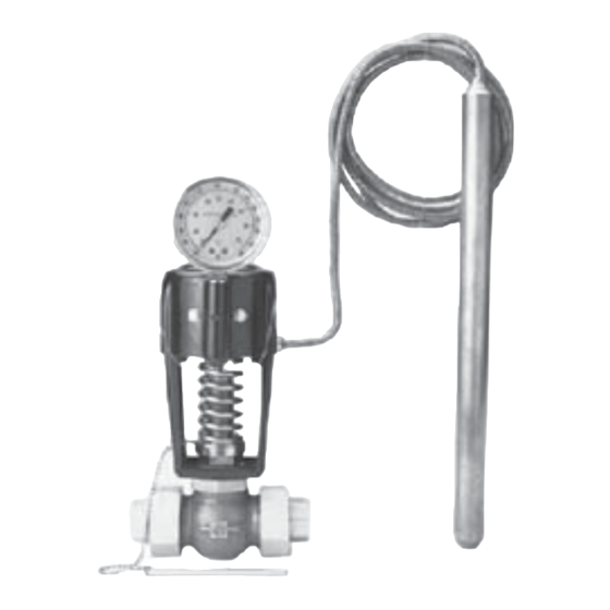
Figure 1. 2000 Series Temperature Regulator
Principle of Operation
The 2000 Series Temperature Regulator controls
the flow of the media passing through its valve by
responding to temperature changes at the temperature
bulb. The valve is made up of two assemblies: the
valve body and the thermal system assemblies.
The thermal system of the 2000 Series temperature
regulator consists of a temperature probe (bulb),
pressure chamber (bellows) and a length of tubing
(capillary) which connects the two. A liquid is sealed
inside the thermal system. For each temperature
range, a specific liquid is used.
www.SpenceValve.com
2000 Series
Advertisement
Table of Contents

Related Manuals for SPENCE 2010


Summary of Contents for SPENCE 2010
- Page 1 The valve is made up of two assemblies: the valve body and the thermal system assemblies. Product Description The thermal system of the 2000 Series temperature regulator consists of a temperature probe (bulb), The 2000 Series is a self-operated temperature...
-
Page 2: Specifications
2000 Series Specifications The Specifications section gives some general specifications for the 2000 Series Temperature Regulator. The nameplates give detailed information for a specific pilot as built in the factory. Available Configurations Pressure Ratings Type 2010: Single seat, direct-acting See Table 1... -
Page 3: Installation
2000 Series INLET DIVERTER OUTLET MIXING Figure 2. 2000 Series Temperature Regulator Operation Installation Type 2050 Three-way Valve (Figure 3) The Type 2050 three-way valve meets most ▲ WARNING mixing or diverting application requirements. When used for mixing, the forces developed by... - Page 4 Spence heating coils. Designer’s Guide. Plain bulbs (standard for 2000 Series), without a union 5. To avoid stresses on the valve or unions, cut the bushing, are used in open tanks, ovens, drying, rooms, connecting pipes to the exact length required and kilns, etc.
- Page 5 STRAINER CHECK VALVE SPENCE FTS STEAM TRAP CHECK VALVE SPENCE STRAINER PRESSURE RELIEF VALVE CONDENSATE MAIN Figure 4. 2000 Series Temperature Regulator Installation TYPE 2050 INDICATING DIVERTING REGULATOR BULB OUTLET TYPE 2050 INDICATING MIXING REGULATOR STORAGE TANK INLET OUTLET BULB...
- Page 6 2000 Series Table 2. Location of Jam Nut on Bulb UNION BUSHING OR WELL BULB DIAMETER RED DOT Small 11-7/8 Large 13-7/8 Extra long 17-3/8 JAM NUT Figure 7. Bulb Union Bushings (Figure 7) Replacement Thermal Systems When a union bushing is required for the bulb, the...
-
Page 7: Regulator Setting
18 to 60 18 to 77 116 to 154 116 to 171 - Control points at these settings are slightly below the low end of the regulator range. Table 5. 2000 Series Bulb Ranges BULB RANGES MAXIMUM OVER TEMPERATURE Short Long °F... -
Page 8: Valve Type
This limiting temperature is, therefore, the maximum 2. Check the controlled temperature and make fine allowable temperature on 2000 Series Regulators adjustments. The arm extending out from the supplied with bulbs as indicated in Table 5. -
Page 9: Maintenance
Bonnet the regulator leaves the factory. “V” Packing Assembly Nuts The Spence Strainer protects the valve disc and Frame seat of the regulator from the destructive effects of Mounting Screws scale, etc. The strainer should be blown out at regular Lock Washer intervals by removing the plug. -
Page 10: Replacement Kit
Thermal System Non-Indicating - 15’ Bronze Thermal System Non-Indicating - 15’ Stainless steel 1. Refer to Type Number Code on 2000 Series Bulletin to add appropriate letter for temperature range. Table8. 2000 Series Replacement Kit Part Numbers VALVE SIZE REPLACEMENT KIT... - Page 11 2000 Series THERMAL ASSEMBLY KIT SAFETY SPING KIT FRAME KIT INDICATOR KIT “V” PACKING KIT BONNET KIT STEM GUIDE KIT (2 SETS) BODY ASSEMBLY KIT Figure 8. 2000 Series Temperature Regulator Assembly...
- Page 12 SpenceValve.com VCIMD-17086 © 2022 Emerson Electric Co. All rights reserved. 05/22 Spence is a mark owned by one of the companies in the Emerson Automation Emerson Automation Solutions Solutions business unit of Emerson Electric Co. The Emerson logo is a trademark and service mark of Emerson Electric Co.
Need help?
Do you have a question about the 2010 and is the answer not in the manual?
Questions and answers