
Related Manuals for M-Tec 10kW-3P

Summary of Contents for M-Tec 10kW-3P
- Page 1 Energy Butler Hybrid Series Energy Butler Series USER MANUAL September 2021 User Manual...
- Page 2 Energy Butler Hybrid Series To secure the full 10-years battery product warranty, be sure to install the M-TEC three phase Energy Butler Series hybrid storage system by qualified installers. Warning: Read this entire document before installing or using M-TEC three phase Energy Butler Series Hybrid storage system. Failure to do so or to follow any of the instructions or warnings in this document can result in electrical shock, serious injury, or death, or can damage M-TEC three phase Energy Butler Series Hybrid storage system, potentially rendering it inoperable.
-
Page 3: Table Of Contents
Energy Butler Hybrid Series CONTENTS -------------------------------------------------------4 1. Im portant Safety Instructions -------------------------------------------------------------------8 2. Inverter Introduction ---------------------------------------------------------------------------8 2.1 Basic features -------------------------------------------------------------12 2.2 Appearance Introduction ----------------------------------------------------------------------14 2.3 Display Interface -------------------------------------------------------------------------15 2.4 Specifications ------------------------------------------------------------------17 2.5 Standard Packing List ------------------------------------------------------------------18 3. Batter y Introduction -------------------------------------------------------------18 3.1 Appearance Introduction -------------------------------------------------------------------------21... -
Page 4: Important Safety Instructions
M-TEC three phase Energy Butler Series Hybrid storage system installation and repair instructions assume knowledge of high voltage electricity and should only be performed by M-TEC Certified Installers. M-TEC assumes no liability for injury or property damage due to repairs attempted by unqualified individuals or a failure to properly follow these instructions. These warnings and cautions must be followed when using our product. - Page 5 Energy Butler Hybrid Series Symbols on the Hybrid Inverter Power indicator. Grid status indicator. Inverter status indicator. Battery SOC and status indicator. Grounding symbol, the inverter casing needs to be properly grounded. Symbols on the Packing box Handle with care. This side up.
- Page 6 Warning: To protect M-TEC LFP Battery and its components from damage when transporting, handle with care. Do not impact, pull, drag, or step on M-TEC LFP Battery. Do not subject M-TEC LFP Battery to any strong force. To help prevent damage, leave M-TEC LFP Battery in its shipping packaging until it is ready to be installed.
- Page 7 M-TEC parts or accessories, or parts or accessories not purchased directly from M-TEC or a M-TEC-certified party. Caution: Do not place M-TEC LFP Battery in a storage condition for more than one (1) month, or permit the electrical feed on the M-TEC LFP Battery to be severed for more than one (1) month, without placing M-TEC LFP Battery into a storage condition in accordance with M-TEC’s storage specifications.
-
Page 8: Inverter Introduction
Applicable Grid Type The applicable grid types of the M-TEC 10kW are TN-S, TN-C, TN-C-S and TT. When applied to the TT grid, the voltage of N to PE should be less than 30V. - Page 9 Energy Butler Hybrid Series Operation Modes M-TEC Hybrid inverter has the following basic operation modes and you can configure the operation mode as per your preference in the App. 1/5 Maximun Solor Self-consumption In this working mode, when the power from the PV array is sufficient, PV power will supply the loads, battery, and grid by the following sequence: Loads>Battery>Grid.
- Page 10 Energy Butler Hybrid Series 3/5 UPS Power Back-up In this working mode, the inverter will use the power from PV or grid (Set by App) to charge the battery with full power and top priority until it is fully charged, and as long as the grid is there, the battery won’t discharge. When the grid is cut off, power from PV and battery will suppy real-time loading connected to inverter back-up port immediately within 10ms.
- Page 11 Off-grid peak load capability M-TEC hybrid inverter supports max 2 times off-grid instantaneous overload of rated output power, and each phase support 1.25 times continuous overload of rated output power but only one of them can reach 1.25 times output power at the same time.
-
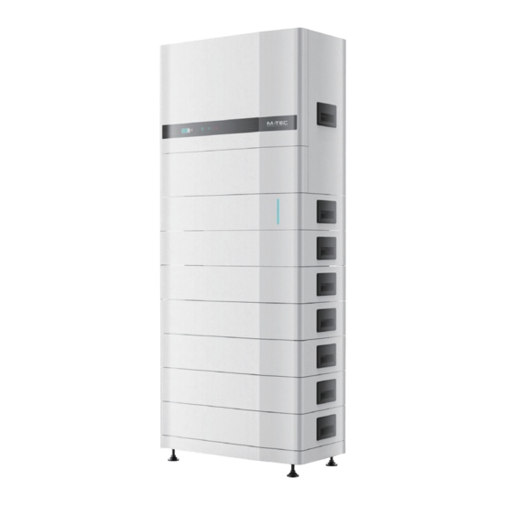
Page 12: Appearance Introduction
Energy Butler Hybrid Series 2.2 Appearance Introduction Front Right side ① ② 698mm 356mm Bottom ④ ③ Inverter in all-in-one kit ① Display ② ⑫ Handle ③ Bottom(with inverter) Inverter positioner ④ Reserved connection hole ⑤ DC Switch(PV) ⑥ METER DC Input Terminal(PV) WiFi/GPRS ⑦... - Page 13 Energy Butler Hybrid Series Inverter Front Right side Bottom METER WiFi/GPRS PV2B Back 550mm User Manual...
-
Page 14: Display Interface
Energy Butler Hybrid Series 2.3 Display Interface Power Indicator Display Grid Indicator Battery SOC and Status Indicator Alarm Indicator Button Item Indicator Status Description Battery not connected or communication fault. Battery SOC and Always on Battery is discharging or waiting, indicator shows battery SOC. Status Indicator Single indicator Battery is charging, indicator shows battery SOC. -
Page 15: Specifications
Energy Butler Hybrid Series 2.4 Specifications Model 6kW-3P 8kW-3P 10kW-3P 12kW-3P Efficiency Max. Input Power (W) 7,800 10,400 13,000 15,600 Start-up Voltage (V) Max. DC Input Voltage (V) 1,000 1,000 1,000 1,000 Rated DC Input Voltage (V) MPPT Voltage Range (V) 200-850 200-850 200-850... - Page 16 Energy Butler Hybrid Series Model 6/8/10/12KW-3P Efficiency Max. Efficiency 98.2% European Efficiency 97.4% Max. Battery Charging Conversion Efficiency 97.3% Max. Battery Discharge Conversion Efficiency 97.3% Protection DC Reverse Polarity Protection Integrated Battery Input Reverse Connection Protection Integrated Insulation Resistance Protection Integrated DC Switch Optional...
-
Page 17: Standard Packing List
The package of the inverter includes the following accessories. Please check whether the accessories in the packing box are complete at the first time when receiving the goods. Inverter in all-in-one kit×1 PV Terminal Expansion Bolt M-TEC Meter with 3 CTs Cord End Terminal AC Cover, Screw PE Terminal On Grid AC Terminal... -
Page 18: Battery Introduction
Energy Butler Hybrid Series 3. Battery Introduction 3.1 Appearance Introduction ① ② ③ ④ ⑤ ⑥ Left side Front ⑦ ⑧ 356mm 698mm Bottom ⑩ ⑪ ⑨ ⑫ ⑬ Sub-Master BMS ① Inverter positioner ② Inverter COM ③ Service COM ④... - Page 19 Energy Butler Hybrid Series ① ② ③ ④ ⑤ ⑥ ⑦ ⑧ ⑨ Front Right side ⑩ 698mm 356mm Bottom ⑪ ⑫ ⑬ ⑭ ⑮ Battery module ① Battery positioner plug ② Terminal positioner plug ③ Earth cable ④ BMU Power Supply - ⑤...
- Page 20 Energy Butler Hybrid Series ① ② ③ ④ ⑤ ⑥ ⑦ 698mm 356mm Base module ① Battery positioner plug ② Terminal positioner plug ③ Earth cable ④ CAN COM Resistor(Pre-installed) ⑤ CAN COM Resistor(Pre-installed) ⑥ Battery Positive B+ ⑦ Battery Positive B+ User Manual...
-
Page 21: Specifications
10,000 Cycles within 10 Years Guarantee * Battery System Configuration Options: 230V/11.5kWh, 307V/15.3kWh, 384V/19.2kWh, 460V/23.0kWh, 537V/26.8kWh, 614V/30.7kWh. * M-TEC reserves the right to modify the technical datasheet and apperance of the product in the manual without prior advice to the users. User Manual... -
Page 22: Standard Packing List
Energy Butler Hybrid Series 3.3 Standard Packing List Main units Sub-Master BMS(BCU) 3.84KWH Li-HV LFP Battery Modules (Stackable) Base for Stackable Li-HV all-in-one system Standard Accessories 300MM Communication Cables from Battery to Inverter Grounding Wire 300mm from Battery to Inverter 300MM Positive Power Cables from Battery to Inverter 300MM Negative Power Cables from Battery to Inverter M6 Plastic Expansion Pipe and Self-tapping Screw... -
Page 23: Mechanical Installation
4. Mechanical Installation 4.1 Selection of Installation Location The M-TEC hybrid inverter is designed with IP65 protection for indoor and outdoor installations. When selecting an inverter installation location, the following factors should be considered: The wall on which the inverter is mounted must be strong and can withstand the weight of the inverter for a long time. -
Page 24: General Installation Steps
Energy Butler Hybrid Series 4.2 General Installation Procedure Installation procedure summary 1. Install the base; 2. Install the battery module and Sub-Master BMS; 3. Install the inverter; 4. Cables connection; 5. Install the cables cover and wall mounting support. System component ①... - Page 25 Energy Butler Hybrid Series Step1. Install the base Check the installation environment to ensure ground level. Place the base on the ground, and make sure it is level and stable. Step2. Install the battery module and Sub-Master BMS After the base is installed, the remaining battery and Sub-Master BMS are then placed in turn. Once each battery or Sub-Master BMS is in place, tighten it with four m4 screws on the left and right side.
- Page 26 Energy Butler Hybrid Series Step3. Install the inverter After the inverter is installed to the All-in-One Kit, put the All-in-One Kit to the stacked battery and Sub-Master BMS. Step4. Install the kit for wall mounted and cables cover Monuting the kit for wall mounted, and tighten them with M6 plastic expansion pipes and self-tapping screws and screws.
-
Page 27: Cables Connection
Energy Butler Hybrid Series 4.3 Cables Connection After mechanical installation is finished, there are positive power line, negative power line, communication cable and earth cable between inverter and Sub-Master BMS need to be connected. The picture on this page shows the cables connection. Please follow the instruction and make sure all the cables are connected correctly. -
Page 28: Inverter Cables Connection
Attention: Do not use other brands or other types of PV terminals other than the PV terminal in the accessory package. M-TEC has the right to refuse all damages caused by the mixed-use of terminals. - Page 29 Main Switch/Breaker RJ45-Meter PV1+ CT-1 Array PV1- ON-GRID CT-2 Grid CT-3 PV2+ Array PV2- Switch/Breaker N-BAR M-TEC Hybrid E-BAR Inverter Normal Loads The additional Battery grounding hole Breaker RJ45-BMS Communication BACK-UP Back-up Loads This diagram is an example for Australia and New Zealand. Neutral line of AC supply must not be isolated or switched.
- Page 30 Energy Butler Hybrid Series Ground terminal connection steps: 1) The external grounding terminal is located in the lower right side of the inverter. 2) Fix the grounding terminal to the PE wire with a proper tool and lock the grounding terminal to the grounding hole in the lower right side of the inverter.
- Page 31 Energy Butler Hybrid Series DC connector assembly procedures 1) Select the appropriate photovoltaic cable: Cable type Conductor transverse area(mm²) Scope(mm²) Recommended value(mm²) General photovoltaic cable 2.5-4.0 2) Peel off the DC cable insulation sleeve for 7 mm. Wire transverse area 2.5-4mm2 3) Disassemble the connector in the accessory bag.
- Page 32 4) Make sure the maximum input voltage of battery is within the inverter limitation (180~750V). For 3.84kWh LFP module, the operation voltage range of each battery module is 60V~87.6V, so usually suggested to series connected 3 to 8 modules for M-TECH Energy Butler Series. User Manual...
- Page 33 Energy Butler Hybrid Series Lithium battery connector assembly procedures 1) Select an appropriate DC cable. Cable type Conductor transverse area(mm²) Outside diameter (mm²) Conductor core section (mm²) AWG 10 5.5-8.0 4.0-6.0 2) Peel off the DC cable insulation sleeve for 7 mm. Wire transverse area 5.5-8.0mm2 15mm 3) Use a flathead screwdriver to open the clamping bracket in the connector.
- Page 34 2) Before making the connection of AC cable, please confirm all DC & AC power source are disconnected from the inverter. 3) The M-TEC Energy Butler three-phase high voltage hybrid inverter applies to the three-phase power grid with a voltage of 230/400V and a frequency of 50/60Hz.
- Page 35 Energy Butler Hybrid Series 1) According to the table above, select an appropriate AC cable, peel off the insulation sleeve of AC cable for 40~60mm, and peel off the sleeve in the conductor core of 3L/PE/N wires for 8mm. Strip Length:8mm Wire Diameter:12-18mm 40-60mm 2) Insert the stripped AC cables through the AC connector cover in the sequence.
- Page 36 Energy Butler Hybrid Series 4) Lock the well-pressed cord end terminals into the AC connector in the accessory bag and make sure the cables sequence is in line with the mark on the connector. 5) Insert the assembled AC connector to the corresponding AC port in the inverter. ON-GRID BACK-UP Caution: Please distinguish the on-grid and back-up port, and don’t mix up the on-grid port and back-up port when making...
- Page 37 1) The current transducer, also called CT, is usually installed on the fire wires between the house loads and the power grid. The Meter can install in the AC combiner box or other places that are unable to be touched by children. M-TEC CT integrated a cable with length of 2m and could be extended to 5m at max.
- Page 38 Energy Butler Hybrid Series 2) The three CTs have already well-connected on the Meter while you received, and you just need to follow the wiring diagram in the Meter to connect CT. Meter terminals definition RS485 5 6 7 Definition Function L1/L2/L3/N connect to grid to detect power grid voltage L1-S1...
-
Page 39: Communication Connection
Energy Butler Hybrid Series 5.2 Communication Connection Communication wiring illustration All communication ports are hidden behind the communication terminal in the bottom of inverter which are include Meter port, CAN port, BMS port, EMS port, relay output port, DRED port. BMS COM Cable Screw cap Screw... - Page 40 Energy Butler Hybrid Series Dismantle the cover of the communication ports with a screwdriver, and put all communication cables through the holes and follow the illustration below to make the connection of each communication cables, and when all cables have connected, put back the cover and screw up the anti-water cap of the holes.
- Page 41 BMS. Note: Before purchasing the battery, you have to make sure the battery you selected is in the battery approval list of M-TEC, otherwise, the system may not work properly. Please contact your installer or M-TEC service team for confirmation if you’re not sure about it.
- Page 42 One key to shut off M-TEC hybrid inverter comes with one key to shut off function, and you can use this function by connecting an external switch into the DRED interface if it requires in the installation place. The external switch doesn't include in our accessory box.
-
Page 43: Monitoring Device Installation
Energy Butler Hybrid Series 5.3 Monitoring Device Installation M-TEC Energy Butler Series hybrid inverter can be monitored through either WiFi or LAN, and you can alternatively select according to your preference. Plug the WiFi or LAN module into the WiFi/GPRS port in the bottom of inverter by following the direction the side with indicator is up. -
Page 44: System Start And Stop
Energy Butler Hybrid Series 6. System Start and Stop Start Inverter Please make sure all cables(PV/Battery/Grid/Back-up) are correctly connected according to above instructions before start up the inverter, or it will has high risk to damage inverter or batteries. Before starting the inverter, follow these steps: 1) Turn the DC switch in the inverter bottom to the “ON”... -
Page 45: General Operation
Energy Butler Hybrid Series 7. General Operation 7.1 Display Operation When the inverter is turned on, the following interfaces will be displayed on the OLED display, and you can check the information and modify the parameters of the inverter by short or long pressing the button. Please refer to the following display operation flow for details. -
Page 46: Auto-Test
7.3 Monitoring and Configuration M-TEC inverter provides a monitoring port that can collect data from the inverter and transmit it to monitoring website via an external monitoring data collector WiFi or LAN module. Please check the WiFi user manual for more details. -
Page 47: Troubleshooting
8.1 Fault Messages M-TEC 10kW three-phase hybrid inverter is designed in accordance with grid operation standard, and conform to the requirements of the safety and EMC. The inverter had passed a series of rigorous tests to ensure it runs sustainably and reliably before shipment. -
Page 48: Maintenance
Attention: As the inverter contains no component parts that can be maintained, never arbitrarily replace any internal components. Attention: For any maintenance need, please contact us. Otherwise, M-TEC shall not be held liable for any damage caused. Note: Servicing of the device in accordance with the manual should never be undertaken in the absence of proper tools, test equipment or the latest revision of the manual which has been clearly and thoroughly understood. - Page 49 Energy Butler Hybrid Series Tel.: +43 7612 20805 Website: http://www.mtec-wp.com Address: Aumühlweg 20, 4812 Pinsdorf User Manual...
Need help?
Do you have a question about the 10kW-3P and is the answer not in the manual?
Questions and answers