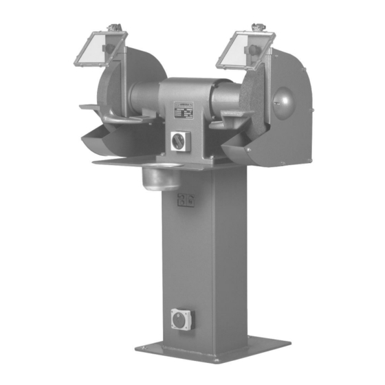
Summarization of Contents
Operator's Guide
Operation
Grind with light pressure, avoid uneven grinding, and ensure the machine runs at max speed before use.
Safety Rules for Stationary Power Tools
Follow 18 safety rules for best results and to avoid misuse and danger.
Maintenance
Place in a dry area. Dress grinding wheel regularly. Change if worn over 25%. Replace damaged parts immediately.
Belt arm
Assembling and Mounting of the Belt Arm
Mount telescope arm on bearing end shield and box cover. Ensure top roll and contact wheel run parallel.
Changing the Grinding Belt
Open lid, loosen handle, dismount belt. Fit new belt ensuring correct rotation direction.
Maintenance of the Belt Arm
Empty spark arrester. Check suction channels. Replace worn contact wheel or graphite pad.
Operating the Belt Arm
Grind at contact wheel or on belt alone. Use light, firm pressure. Avoid uneven grinding and motor overload.
KU 12-Exhaust System
Assembling and Mounting the KU 12-Exhaust Unit
Mount angle, connector, protection hose, and switch. Connect suction hoses to outlet or dust bags.
Maintenance of the KU 12-Exhaust Unit
Check suction hoses for good condition. Ensure suction channels are clean.
16-Exhaust Unit
Maintenance of EX-16-Exhaust Unit
Examine suction hoses. Clean suction channels. Check and change dust bag regularly.
Spare Parts List
Machine Display and Overview
Illustrated split drawings of the machine models with identified parts.
E 312 Basic Model Split Drawing
Exploded view diagram of the E 312 basic model with numbered components.
E 312 Spare Parts List
List of spare parts for the E 312 model, including position number, description, and item number.
BO 10 Basic Model Split Drawing
Exploded view diagram of the BO 10 basic model with numbered components.
BO 10 Spare Parts List
List of spare parts for the BO 10 model, including position number, description, and item number.
E 312 Cover Split Drawing
Exploded view diagram of the E 312 cover assembly with numbered components.
E 312 Cover Spare Parts List
List of spare parts for the E 312 cover, detailing position, description, and cover type (L/R).
EPB 312 Belt Arm Split Drawing
Exploded view diagram of the EPB 312 belt arm with numbered components.
EPB 312 Belt Arm Spare Parts List
List of spare parts for the EPB 312 belt arm, including position, description, and type number (Right/Left).
POB 312 Belt Arm Split Drawing
Exploded view diagram of the POB 312 belt arm with numbered components.
POB 312 Belt Arm Spare Parts List
List of spare parts for the POB 312 belt arm, including position, description, and type number (Right/Left).
KU 12-Exhaust Unit Split Drawing
Exploded view diagram of the KU 12-exhaust unit for EP 312 with numbered components.
KU 12-Exhaust Unit Spare Parts List
List of spare parts for the KU 12-exhaust unit for EP 312, including part number and description.
EX-16-Exhaust Unit Split Drawing
Exploded view diagram of the EX-16-exhaust unit for EPX 312 with numbered components.
EX-16-Exhaust Unit Spare Parts List
List of spare parts for the EX-16-exhaust unit for EPX 312, including part number and description.
Technical Data
Technical Specifications
Table detailing technical specifications like motor power, wheel sizes, IP class, and weight for different models.
Dimensions
Diagram and table showing physical dimensions (A-L) for E 312 and EP 312 models.
Wiring Diagram
Wiring diagrams for Max. Voltage and Min. Voltage connections for the grinding machines.
Warranty
Warranty Information
Details warranty terms for machine defects, service, and a five-year guarantee on the electrical motor.


Need help?
Do you have a question about the EP 312 and is the answer not in the manual?
Questions and answers