
Related Manuals for Thermo Electron 905


Summary of Contents for Thermo Electron 905
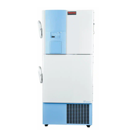
- Page 1 900 Series Forma -86C ULT Freezer Operating and Maintenance Manual Manual No: 7010902 Rev. 8...
- Page 2 The material in this manual is for information purposes only. The contents and the product it describes are subject to change with- out notice. Thermo Electron Corporation makes no representa- tions or warranties with respect to this manual. In no event shall Thermo be held liable for any damages, direct or incidental, aris- ing out of or related to the use of this manual.
- Page 3 Model 900 Series _________________________________________________________________________Warnings Important operating and/or maintenance instructions. Read the accompanying text carefully. Potential electrical hazards. Only qualified persons should perform procedures associated with this symbol. Hot surface(s) present which may cause burns to unprotected skin or to materials which may be damaged by elevated temperatures Extreme temperature hazards, hot or cold.
- Page 4 Model 900 Series ___________________________________________________________________________Service...
-
Page 5: Table Of Contents
Model 900 Series __________________________________________________________________Table of Contents Table of Contents Section 5 - Factory Options ..... .5 - 1 Section 1 - Installation and Start-up ....1 - 1 5.1 BUS (Back Up System) . -
Page 6: Section 1 - Installation And Start-Up
Model 900 Series ___________________________________________________________________Installation and Start-Up Section 1 - Installation and Start-up Figure 1-4 Figure 1-1 Vacuum Relief and Probe Cover Location 900 Series Front 1.1 Freezer Components Figure 1-1 • Control Panel - keypad, displays and indicators • BUS (Optional Back Up System) panel •... -
Page 7: Control Panel Keys, Displays And Indicators
Model 900 Series ____________________________________________________________Installation and Start-Up Figure 1-5 • Battery mounting bracket(s) • Battery power switch (freezer and BUS) • Freezer battery • Optional BUS battery • Freezer filter location Figure 1-5 Battery(s) location and Switch Figure 1-6, Control Panel 1.2 Control Panel Keys, Displays and Indicators... -
Page 8: Operation Of The Keypad
Model 900 Series ___________________________________________________________________Installation and Start-Up 1.3 Operation of the Keypad Figure 1-7 The 900 Series freezer has five basic modes which allow freezer setup and operation. Press the a. Choosing the Location Mode key to scroll through the mode selections. -
Page 9: Remote Alarm Contacts
10° from set point. All 900 Series freezers have an operating temperature range of -50°C to -86°C, depending on ambient temperature. The freezer is shipped from the factory with a temperature set point of -80°C. -
Page 10: Setting The High Temperature Alarm
Model 900 Series ____________________________________________________________Installation and Start-Up b. Setting the High Temperature Alarm 1.7 Run Mode The Run mode is the default mode for the freezer. The run The high temperature alarm will activate an audible/visual mode will display the cabinet temperature on the temperature warning when the freezer chamber temperature has reached or display under normal operating conditions. -
Page 11: Section 2 - Calibrate
Model 900 Series _________________________________________________________________________Calibration Section 2 - Calibrate 2.1 Calibrate Mode Once the freezer has stabilized, the control probe may need to be calibrated. Calibration frequency is dependent on use, ambient conditions and accuracy required. A good laboratory practice would require at least an annual calibration check. On new installations, all parameters should be checked after the stabilization period. -
Page 12: Section 3 - Alarms
3.1 Alarms The Model 900 Series freezer alarms are displayed on the freezer control panel. When an alarm is active, the indicator next to the alarm description will light and there will be an audible alarm. Press the Silence key to disable the audible alarm for the ringback period. -
Page 13: Section 4 - Maintenance
Model 900 Series ______________________________________________________________________Maintenance a. Cleaning the Water-cooled Condenser Section 4 - Maintenance The water-cooled condenser can be cleaned-in-place by using the CIP procedure. Cleaning solutions can be used, 4.1 Cleaning the Cabinet Exterior depending on type of deposits or build-up to be removed. -
Page 14: Cleaning The Door Gasket
Model 900 Series ______________________________________________________________________Maintenance 4.5 Cleaning the Door Gasket (minimum monthly) Using a soft cloth, remove any frost build-up from the gas- ket and door(s). The door gasket may need to be cleaned more frequently if dirt or excessive frost build-up prevents the door from closing properly. - Page 15 Model 900 Series ______________________________________________________________________Maintenance 5. Verify the vacuum relief Vacuum Relief Port Maintenance mechanism is moving 1. Once the door has opened, inspect the vacuum relief port freely. Depress the valve for ice. Remove inventory racks or any obstructions from and release.
-
Page 16: Replacing The Battery(S)
Model 900 Series ______________________________________________________________________Maintenance 4.7 Replacing the Battery(s) 4.8 Preparing the Unit for Storage 1. To gain access to the battery, open the lower door by grasping Defrost the unit as described in Section 4.4. This will pre- the bottom left corner. The battery is rectangular in shape, pare the unit for storage. -
Page 17: Preventive Maintenance
Model 900 Series ________________________________________________________________________________________________________________Maintenance PREVENTIVE MAINTENANCE Freezers Your equipment has been thoroughly tested and calibrated before shipment. Regular preventive maintenance is important to keep your unit function- ing properly. The operator should perform routine cleaning and maintenance on a regular basis. For maximum performance and efficiency, it is rec- ommended that the unit be checked and calibrated periodically by a qualified service technician. - Page 18 Model 900 Series ________________________________________________________________________________________________________________Maintenance Preventive Maintenance for 900 Series Freezers Refer to Manual Section Action Monthly Yearly Every 2 Years Verify ambient temperature, <90°F * Adjust door handle for firm latching, as needed Figure 1-4 for probe location Check and clean probe cover, gaskets, hinges, inner doors, 4.5, 4.6...
-
Page 19: Section 5 - Factory Options
Model 900 Series ________________________________________________________________________Factory Options Section 5 - Factory Installed Options The BUS operates on an internal 12-volt, rechargeable bat- 5.1 BUS - Back Up System (195875, 195877) tery which is kept charged during normal operation by the inte- gral battery charger. -
Page 20: Installing The Temperature Probe
Model 900 Series ________________________________________________________________________Factory Options 8. Install the transfer hose connecting one end to the injec- tion assembly, the other end to the solenoid valve. Install the solenoid valve to the supply source. The solenoid mounting bracket is not required and may be discarded. -
Page 21: Bus Control Panel
Model 900 Series ____________________________________________________________________Factory Options Figure 5-6 BUS Operation and Maintenance f. Setting the Optional BUS Set Point d. BUS Control Panel (see figure 5-6) The optional back up system is designed to inject CO into the freezer compartment if the temperature rises above WARNING! When activated, this unit injects liq- back up system set point. -
Page 22: Chart Recorder
Model 900 Series ____________________________________________________________________Factory Options Figure 5-7 Recorder Details 5.2 Chart Recorder Program From a. Installing the chart paper 30°C 60°C 1. Open the glass door of the recorder and press button #3 until -100 38°C the pen begins to move outward. -
Page 23: Datalogger
Model 900 Series ____________________________________________________________________Factory Options 5.3 Datalogger Dataloggers and ELPRO evaluation software provide moni- toring and documentation of temperature and alarm conditions. The dataloggers have a memory capacity of 64,000 measured values or data points. Temperature is measured, stored and dis- played. - Page 24 Specifications - Single Door Units Model Temperature -50°C (-58°F) to -86°C (-123°F) in an 18C to 32C* (64.4F to 89.6F) ambient Range Exterior 33.3”W x 77.8”H x 31.0” 33.3”W x 77.8”H x 31.0” 33.3”W x 77.8”H x 37.0” 33.3”W x 77.8”H x 37.0” 40.8”W x 77.8”H x 37.0”...
-
Page 25: Section 6 - Specifications
Model 900 Series _____________________________________________________________________Specifications Certifications Declaration of Conformity is available from the factory Safety Specifications Indoor Use Only Altitude - up to 2,000 meters Temperature - 5°C to 40°C Humidity - Maximum RH 80% for temperatures up to 31°C, decreasing linearly to 50% RH at 40°C Mains Supply Fluctuations - Mains supply voltage fluctuations not to exceed ±10% of the nominal voltage... - Page 26 Model 900 Series ________________________________________________________________________________Parts 7 - 1...
- Page 27 Model 900 Series ________________________________________________________________________________Parts 7 - 2...
- Page 28 Model 900 Series ________________________________________________________________________________Parts Upright Freezer Cabinet Assembly 8602-200-1-B Rev. 2 Page 2 of 2 7 - 3...
- Page 29 Model 900 Series ________________________________________________________________________________Parts 7 - 4...
- Page 30 Model 900 Series ________________________________________________________________________________Parts Upright Freezer Cabinet Assembly Double Door 8602-200-2-B Rev. 2 Page 2 of 2 7 - 5...
- Page 31 Model 900 Series ________________________________________________________________________________Parts 7 - 6...
- Page 32 Model 900 Series ________________________________________________________________________________Parts 7 - 7...
- Page 33 Model 900 Series ________________________________________________________________________________Parts 7 - 8...
- Page 34 Model 900 Series ________________________________________________________________________________Parts 7 - 9...
- Page 37 Model 900 Series ________________________________________________________________________________Parts 7 - 12...
- Page 38 Model 900 Series ________________________________________________________________________________Parts 7 - 13...
- Page 39 Model 900 Series ________________________________________________________________________________Parts 7 - 14...
- Page 40 Model 900 Series ________________________________________________________________________________Parts 7 - 15...
- Page 41 Model 900 Series ________________________________________________________________________________Parts 7 - 16...
- Page 50 Model 900 Series ______________________________________________________________________Electrical Schematics 9 - 1...
- Page 51 Model 900 Series ______________________________________________________________________Electrical Schematics 9 - 2...
- Page 52 Model 900 Series ______________________________________________________________________Electrical Schematics 9 - 3...
- Page 53 Model 900 Series ______________________________________________________________________Electrical Schematics 9 - 4...
- Page 54 Model 900 Series ______________________________________________________________________Electrical Schematics 9 - 5...
- Page 55 Model 900 Series ______________________________________________________________________Electrical Schematics 9 - 6...
-
Page 56: Section 10 - Warranty
During the first two years of the warranty period, component p art s proven to be non-conforming in materials or workmanship will be rep aired or replaced at Thermo's expense, labor included. The 900 Series UL T Freezers include an additional two year warranty on the compressors, p art s only , F .O.B. - Page 57 During the first two years of the warranty period, component p art s proven to be non-conforming in materials or workmanship will be rep aired or replaced at Thermo's expense, labor excluded. The 900 Series UL T Freezers include an additional two year warranty on the compressors, p art s only , F .O.B.
-
Page 58: Appendix A - Handling Liquid Nitrogen
Model 900 Series _____________________________________________________________________________Appendix A Appendix A Handling Liquid Nitrogen Contact of liquid nitrogen or cold gas with the skin or eyes may cause serious freezing (frostbite) injury. Handle liquid nitrogen carefully. The extremely low temperature can freeze human flesh very rapidly. When spilled on a surface the liquid tends to cover it com- pletely and intimately, cooling a large area. - Page 59 Model 900 Series _____________________________________________________________________________Appendix A Introduction The safe handling and use of liquid nitrogen in cryogenic refrigerators and dewar flasks is largely a matter of knowing the potential hazards and using common-sense procedures based on that knowledge. There are two important properties of liquid nitro- gen that present potential hazards: 1.
-
Page 60: Appendix B - Handling Liquid Co
Model 900 Series _____________________________________________________________________________Appendix B Appendix B Handling Liquid Co High concentrations of CO gas can cause asphyxiation! OSHA Standards specify that employee exposure to carbon dioxide in any eight-hour shift of a 40-hour work week shall not exceed the eight-hour time weighted average of 5000 PPM (0.5% CO... -
Page 61: First Aid
Model 900 Series _____________________________________________________________________________Appendix C First Aid If a person seems to become dizzy or loses consciousness while working with liquid nitrogen or carbon dioxide, move to a well- ventilated area immediately. If breathing has stopped, apply artificial respiration. If breathing is difficult, give oxygen. Call a physician. - Page 66 Thermo Electron Corporation Controlled Environment Equipment Millcreek Road, P.O. Box 649 Marietta, Ohio 45750 U.S.A. Telephone (740) 373-4763 Telefax (740) 373-4189...
Need help?
Do you have a question about the 905 and is the answer not in the manual?
Questions and answers