Table of Contents
Advertisement
SERVICE MANUAL
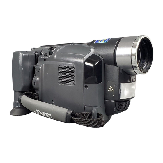
COMPACT VHS CAMCORDER
GR-AXM236U,AXM240U,SXM240U
SXM245U,SXM248U
AXM341U,SXM540U,SXM745U
Regarding service information other than these sections, refer to the GR-SXM340U and GR-SXM740U service manual (No. 86656).
Also, be sure to note important safety precautions provided in the service manual.
SPECIFICATIONS
Camcorder
General
Format
: S-VHS/VHS NTSC standard
Power source
: DC 11 V
DC 6 V
Power consumption
Viewfinder on
: 4.0 W
LCD monitor on
: 4.5 W
Video light
: 3.0 W
Signal system
: NTSC-type
Video recording system
Luminance
: FM recording
Color
: Converted sub-carrier direct recording
Conforms to VHS standard
Cassette
:
/
Tape speed
SP
: 33.35 mm/sec. (1-5/16 ips)
EP
: 11.12 mm/sec. (7/16 ips)
Recording time (max.)
SP
: 40 minutes
EP
: 120 minutes
(with TC-40 cassette)
Operating temperature : 0°C to 40°C (32°F to 104°F)
Operating humidity
: 35% to 80%
Storage temperature
: –20°C to 50°C (–4°F to 122°F)
Weight
: Approx. 930 g (2.1 lbs)
Dimensions
: 200 mm x 112 mm x 118 mm (7-7/8" x 4-7/16" x 4-11/16")
(W x H x D)
(with the LCD monitor closed and with the viewfinder fully
tilted downward)
Pickup
: 1/4" format CCD
Lens
: F1.6, f = 3.9 mm to 62.4 mm,
16:1 power zoom lens with auto iris and macro control, filter
diameter 40.5 mm
Viewfinder
: Electronic viewfinder with 0.5" black/white CRT
White balance
adjustment
: Auto/Manual adjustment
(The specifications shown pertain specifically to the model GR-SXM745U)
(Using AC Adapter)
(Using battery pack)
cassette
This service manual is printed on 100% recycled paper.
COPYRIGHT © 2001 VICTOR COMPANY OF JAPAN, LTD.
LCD monitor
: 3.5" diagonally measured, LCD panel/TFT active
matrix system
Speaker
: Monaural
Connectors
: 1 V (p-p ) , 75 Ω unbalanced, analog output (via Video
Video
output connector)
Audio
: 300 mV (rms), 1 kΩ analog output
(via Audio output connector)
Digital
: ø3.5 mm, 4-pole, mini-head jack
: Y : 1 V (p-p), 75 Ω, analog output
S-Video
C : 0.29 V (p-p ) , 75 Ω, analog output
AC Adapter
Power requirement
U.S.A. and Canada
: AC 120 V`, 60 Hz
Other countries
: AC 110 V to 240 V`, 50 Hz/60 Hz
Output
: DC 11 V
Optional Accessories
• Battery Packs BN-V12U, BN-V20U, BN-V400U
• A/V (Audio/Video) Cable
• Compact S-VHS (
) Cassettes
ST-C-40/30/20
• Compact VHS (
) Cassettes TC-40/30/20
• Active Carrying Bag CB-V7U
Some accessories are not available in some areas. Please consult your
nearest JVC dealer for details on accessories and their availability.
Specifications shown are for SP mode unless otherwise indicated.
E & O.E. Design and specifications subject to change without notice.
, 1 A
No. 86660
December 2001
Advertisement
Table of Contents

Summarization of Contents
SPECIFICATIONS
Camcorder Specifications
Detailed technical specifications for the camcorder's functionality and physical attributes.
LCD Monitor Specifications
Technical details specific to the camcorder's LCD monitor.
Connectors and AC Adapter
Information on the camcorder's ports and power adapter specifications.
Optional Accessories
List of optional accessories available for the camcorder.
INSTRUCTIONS AND OPERATION
AUTOMATIC DEMONSTRATION
Guide for using the camcorder's automatic demonstration mode.
PRECAUTIONS AND SAFETY
GENERAL SAFETY PRECAUTIONS
Essential safety measures and warnings for product use.
IMPORTANT SAFETY INSTRUCTIONS
Comprehensive safety guidelines covering handling, environment, and servicing.
GETTING STARTED
Battery and AC Power Usage
Instructions for using the battery pack and AC adapter for power.
BASIC FEATURES
Snapshot and Picture Stabilization
How to use snapshot for still images and picture stabilizer for steady video.
MENU SETTINGS AND SYSTEM OPTIONS
CAMERA MENU SETTINGS
Detailed explanation of camera settings like focus and exposure.
SYSTEM MENU OPTIONS
Configuration options available in the system menu, including recording modes.
ADVANCED FEATURES
Night-Alive and Video Effects
Guide to using Night-Alive for low light and various fade/wipe video effects.
REMOTE CONTROL OPERATION
Playback Zoom and Editing
How to use the remote for playback zoom, insert editing, and audio dubbing.
TROUBLESHOOTING AND CAUTIONS
TROUBLESHOOTING GUIDE
Solutions for common operational problems and error indications.
GENERAL CAUTIONS
Important warnings regarding battery use, video light, and environmental factors.
LCD MONITOR CARE
Guidelines for preventing damage and maintaining the LCD monitor.
SECTION 1 DISASSEMBLY AND SERVICE
SERVICE CAUTIONS
Safety and handling precautions before performing service.
TOOLS REQUIRED FOR ADJUSTMENTS
List of necessary tools for proper adjustment procedures.
DISASSEMBLY PROCEDURES
Step-by-step guides for disassembling various parts of the camcorder.
REPLACEMENT PROCEDURES
Instructions for replacing specific components like the CCD image sensor.
EMERGENCY AND OPERATIONAL MODES
Information on emergency displays, demonstration mode, and tape handling.
SERVICE NOTES
Important notes and guidelines for service personnel.
SECTION 2 MECHANISM ADJUSTMENT
MECHANISM SERVICE CAUTIONS
Safety precautions specific to service on the camcorder's mechanism.
MECHANISM DISASSEMBLY/ASSEMBLY
Detailed procedure for disassembling and reassembling mechanism parts.
MECHANISM ADJUSTMENT PROCEDURES
Steps for checking and adjusting mechanism phases, tape transport, and heads.
JIG CONNECTOR CABLE CONNECTION
Instructions for connecting test equipment using the jig connector cable.
SECTION 3 ELECTRICAL ADJUSTMENT
ELECTRICAL ADJUSTMENT PREPARATION
Requirements and preparations for performing electrical adjustments.
E. VF SECTION ADJUSTMENT
Specific setup and adjustment procedures for the Electronic Viewfinder.
ELECTRONIC VIEWFINDER ADJUSTMENT
Detailed steps for adjusting tilt, centering, scanning, brightness, and focus.
SECTION 4 SCHEMATICS AND DIAGRAMS
SCHEMATIC DIAGRAM NOTES
Guidelines for interpreting schematic diagrams, symbols, and voltage charts.
CIRCUIT BOARD LAYOUTS
Component placement diagrams for main, monitor, CCD, and E. VF circuit boards.
SYSTEM BLOCK DIAGRAMS
Overall system block diagrams illustrating the camcorder's architecture.
WAVEFORMS AND VOLTAGE CHARTS
Reference material showing signal waveforms and voltage measurements.
SECTION 5 PARTS LIST
PACKING AND ACCESSORY PARTS
List of parts included in the camcorder packaging.
ASSEMBLY PARTS LISTS
Parts lists for major assemblies like Final, Mechanism, Viewfinder, and Monitor.
ELECTRICAL PARTS LIST
Detailed list of all electrical components with part numbers.


Need help?
Do you have a question about the GR-SXM245U and is the answer not in the manual?
Questions and answers