
Related Manuals for Boss 355AA DN25


Summarization of Contents
GENERAL INFORMATION
DESCRIPTION
Describes the normally closed automatic fast opening solenoid valves for gas, their function, and control options.
KEY OF SYMBOLS
Explains the meaning of danger and attention symbols used in the manual for safety and proper understanding.
QUALIFIED STAFF
Defines the qualifications required for personnel performing installation, assembly, start-up, and maintenance.
USING NON-ORIGINAL SPARE PARTS
Warns against using non-original parts, potential warranty voiding, and compromise of correct device operation.
IMPROPER USE
Outlines prohibited uses, exceeding technical data, and manufacturer liability for damage caused by improper operation.
TECHNICAL DATA
MODEL IDENTIFICATION
References Table 2 for details on identifying different valve models based on their specifications.
SIL LEVEL
Details the Safety Integrity Level (SIL) for the solenoid valve, including performance level (PL) and expected lifetime.
COMMISSIONING THE DEVICE
OPERATIONS PRIOR TO INSTALLATION
Lists essential checks and actions to perform before installing the solenoid valve to ensure safety and proper function.
INSTALLATION
Provides instructions and guidelines for correctly assembling and installing the solenoid valve onto the piping system.
INSTALLATION IN PLACES WHERE THERE IS THE RISK OF EXPLOSION
Specifies that the solenoid valve is not suitable for use in potentially explosive areas as per directive 2014/34/EU.
GENERIC EXAMPLE OF AN INSTALLATION
Illustrates a typical installation of the solenoid valve within a burner gas train system with component identification.
FIRST START-UP
RECOMMENDED PERIODIC CHECKS
Outlines recommended checks for ensuring the continued proper operation and tightness of the solenoid valve.
MAINTENANCE
REPLACING THE CONNECTOR
Step-by-step instructions for removing and replacing the electrical connector on the solenoid valve coil.
REPLACING THE COIL
Procedure for safely removing and installing a new electric coil on the solenoid valve assembly.
CPI SWITCH
CPI SWITCH TECHNICAL DATA
Lists the technical specifications for the CPI microswitch, including voltage, current, power, and protection rating.
CPI SWITCH INSTALLATION and CALIBRATION
Detailed guide for installing and calibrating the CPI switch to signal the solenoid valve's closed position.
Drawings
fig. 1 DN 15-20
Detailed diagram of the solenoid valve for DN 15-20 sizes, showing numbered components.
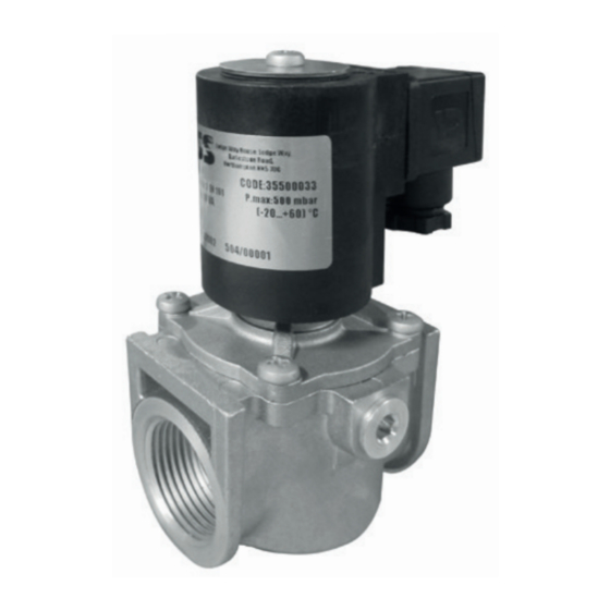
fig. 2 DN 25
Detailed diagram of the solenoid valve for DN 25 size, showing numbered components.
fig. 3 CPI installation
Diagram illustrating the installation of the CPI (Closed Position Indicator) switch.
Overall dimensions
Table 1
Provides overall dimensions in millimeters for different threaded connection sizes of the solenoid valve.
Coils and connectors
Table 2
Lists valve codes, connections, voltage, coil/connector codes, stamping, type, and absorbed power.
Need help?
Do you have a question about the 355AA DN25 and is the answer not in the manual?
Questions and answers