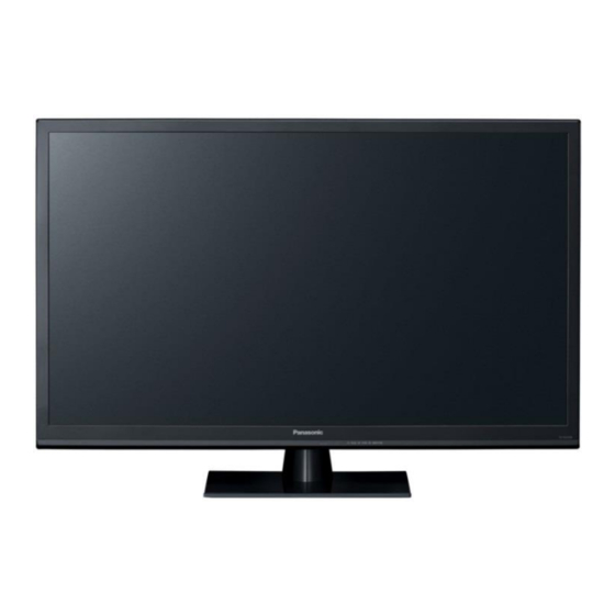
Table of Contents
Advertisement
Service Manual
This service information is designed for experienced repair technicians only and is not designed for use by the general public. It does not
contain warnings or cautions to advise non-technical individuals of potencial dangers in attempting to service a product. Products
powered by electricity should be serviced or repaired only by experienced professional technicians. Any attempt to service or repair the
product or products deal within this service information by anyone else could result in serious injury or death.
There are special components used in this equipment which are important for safety. These parts are marked
Schematic Diagrams, Circuit Board Diagrams, Explorer Views and Replacement Parts List. It is essential that these
critical parts should be replaced with manufacturer´s specified parts to prevent shock, fire or other hazards. Do not
modify the original design without permission of manufacturer.
TX-24CR300 / TX-24CR300
TX-24CW304 / TX-32C300
TX-32CW304 / TX-40C300
TX-40CW304 / TX-40CR300
TX-48CW304 / TX-48C300
TX-48CR300
Warning
IMPORTANT SAFETY NOTICE
0
ORDER No. MQM1505001V2
LCD Television
MB97 Chassis
© Panasonic Corporation 2015.
Unauthorized copying and
distribution is a violation of law.
in the
Advertisement
Table of Contents

Summarization of Contents
Safety Precautions
General Guide Lines
General servicing rules and checks to ensure safety during and after repairs.
Touch Current Check Procedure
Details the process for measuring touch currents to prevent shock hazards.
Electrostatic Discharge (ESD) Prevention
ESD Handling Techniques
Essential methods to prevent damage to sensitive electronic components from static electricity.
Lead Free Solder (PbF) Information
PbF Solder Characteristics
Explains the properties, melting point, and handling precautions for lead-free solder.
Service Navigation and Board Layout
Chassis Board Layout Overview
Illustrates the placement of major internal components for different TV models.
Service Hints and Procedures
Spareparts Identification Method
Guides on correctly identifying parts using model and product codes from the rating label.
Pedestal and Backcover Removal (24 inch)
Step-by-step instructions for disassembling the pedestal and backcover of the 24-inch model.
Pedestal and Backcover Removal (32, 40, 48 inch)
Step-by-step instructions for disassembling the pedestal and backcover of larger models.
Service Menu Operations
Accessing the Service Menu
Describes the key sequence to enter and exit the service menu for adjustments.
Service Menu Video Settings
Details adjustable video parameters available within the service menu interface.
Diagnostic and Software Update
Diagnostic Test Functions
Lists available diagnostic tests including remote control, pattern, and factory reset.
Main Software Update Procedure
Outlines the steps for updating the TV's main software via a USB flash drive.
Hotel Mode Configuration
Hotel TV Feature Overview
Explains the purpose and basic restrictions of the hotel mode for guest use.
Hotel TV Menu Access and Settings
Details how to enter the hotel menu and configure core settings like volume and panel lock.
Hotel Mode Specific Settings Part 1
Covers volume limits, headphone control, OSD, teletext, and wake-up functions.
Hotel Mode Specific Settings Part 2
Covers remote control support, welcome messages, signal status, and system resets.
Component Parts Location
Internal Parts Identification Diagram
Visually identifies key internal components like speakers, switches, and connectors by position.
Lead Wiring Location (24 inch)
Internal Wiring Connections Diagram
Shows the routing and connection points of internal cables for the 24-inch model.
Lead Wiring Location (32 inch)
Internal Wiring Connections Diagram
Shows the routing and connection points of internal cables for the 32-inch model.
Lead Wiring Location (40 inch)
Internal Wiring Connections Diagram
Shows the routing and connection points of internal cables for the 40-inch model.
Lead Wiring Location (48 inch)
Internal Wiring Connections Diagram
Shows the routing and connection points of internal cables for the 48-inch model.
General Block Diagram
System Interconnection Overview
Provides a high-level schematic of the TV's functional blocks and signal flow.
Exploded View (24 inch)
Disassembly Parts Identification
Illustrates the parts and their order for the 24-inch model's disassembly.
Exploded View (32, 40, 48 inch)
Disassembly Parts Identification
Illustrates the parts and their order for larger models' disassembly.


Need help?
Do you have a question about the TX-32C300 and is the answer not in the manual?
Questions and answers