Table of Contents
Advertisement
Quick Links
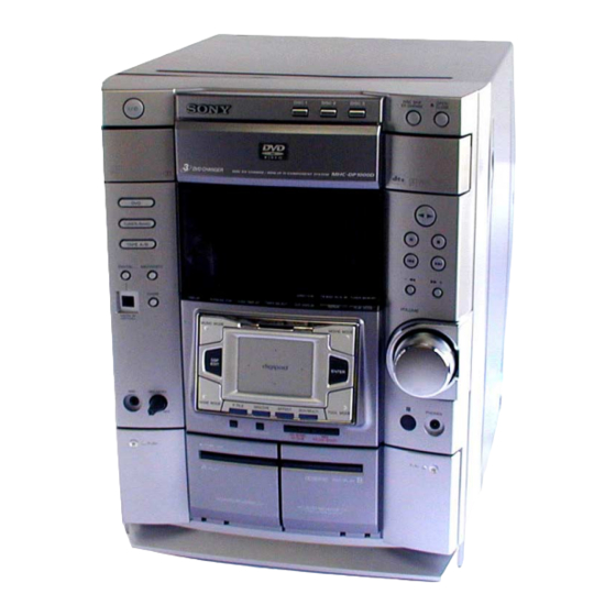
SERVICE MANUAL
Ver 1.0 2001. 09
• MHC-DP1000D is composed of following models.
As for the service manual, it is issued for each component model,
then, please refer to them.
COMPONENT MODEL NAME
DVD DECK
RECEIVER SYSTEM
SS-DP1000DW (US,CND,AEP,UK)
FRONT SPEAKER
SS-DP1000D
REAR SPEAKER
SPEAKER
SS-RC270
SYSTEM
CENTER SPEAKER
SPECIFICATIONS
General
Power requirements
North American model:
European model:
Australian model:
Mexican model:
Thailand model:
Indian, Pakistani, Moroccan and Tunisian models:
Other models:
Power consumption
U.S.A. model:
Canadian model:
European model:
Other models:
Dimensions (w/h/d)
Mass
North American and European models:
Other models:
Supplied accessories:
Design and specifications are subject to change without notice.
Sony Corporation
9-873-315-01
2001I0200-1
Home Audio Company
© 2001.9
Sinagawa Tec Service Manual Production Group
MHC-DP1000D
HCD-DP1000D
(EXCEPT US,CND,AEP,UK)
SS-RS270
SS-CT270
120 V AC, 60 Hz
230 V AC, 50/60 Hz
230 – 240 V AC,
50/60 Hz
120 V AC, 60 Hz
220 V AC, 50/60 Hz
220 V AC, 50/60 Hz
120 V, 220 V or
230 – 240 V AC,
50/60 Hz
Adjustable with voltage
selector
205 watts
205 watts
190 watts
0.5 watts (at the Power
Saving Mode)
225 watts
Approx. 280 x 360 x 365mm
Approx. 11.0 kg
12.0 kg
AM loop antenna (1)
FM lead antenna (1)
Remote commander (1)
Batteries (2)
Video cable (1)
Front speaker pads (8)
Center and rear speaker
pads (12)
• Abbreviation
CND: Canadian model
SP : Singapore model
MY : Malaysia model
EA : Saudi Arabia model
PARTS LIST
Part No.
Description
Remark
ACCESSORIES
************
1-476-445-11
REMOTE COMMANDER (RM-SD270)
1-501-374-11
ANTENNA, LOOP
1-501-594-11
ANTENNA (FM)(AEP,UK)
1-501-659-71
ANTENNA (FM)(EXCEPT AEP,UK)
1-558-848-11
CORD, SPEAKER (SS-DP1000D/DP1000DW)(3m)
1-769-433-11
CORD, SPEAKER (SS-RS270) (10m)
1-769-433-41
CORD, SPEAKER (SS-CT270) (2.5m)
1-782-981-21
CORD, CONNECTION
4-210-254-01
CUSHION (FOOT)
4-232-032-01
COVER, BATTERY (FOR RM-SD270)
4-232-734-11
MANUAL, INSTRUCTION (SS-DP1000DW)
(ENGLISH,FRENCH,GERMAN,SPANISH,DUTCH,SWEDISH,
ITALIAN,PORTUGUESE,TURKISH,POLISH,HUNGARIAN,
GREEK,FINNISH,DANISH,CZECH,RUSSIAN)
4-232-961-01
FOOT (SS-RC270)
4-236-762-11
MANUAL, INSTRUCTION (ENGLISH)
4-236-762-21
MANUAL, INSTRUCTION (FRENCH)(CND,EA)
4-236-762-31
MANUAL, INSTRUCTION (SPANISH)(MX)
4-236-762-41
MANUAL, INSTRUCTION (ENGLISH,FRENCH,SPANISH)
4-236-762-51
MANUAL, INSTRUCTION (GERMAN,DUTCH,ITALIAN)(AEP)
4-236-762-61
MANUAL, INSTRUCTION (SWEDISH,POLISH)(AEP)
4-236-762-71
MANUAL, INSTRUCTION (ARABIC)(EA)
4-236-762-81
MANUAL, INSTRUCTION (TRADITIONAL CHINESE)(SP,MY)
4-236-763-11
MANUAL, INSTRUCTION (DANISH,FINNISH)(AEP)
4-236-763-21
MANUAL, INSTRUCTION (PORTUGUESE)(AEP)
4-236-763-31
MANUAL, INSTRUCTION (GREEK)(AEP)
4-236-763-41
MANUAL, INSTRUCTION (HUNGARIAN,CZECH)(AEP)
4-236-763-51
MANUAL, INSTRUCTION (TURKISH)(AEP)
4-236-763-61
MANUAL, INSTRUCTION (SLOVAK)(AEP)
4-236-764-11
MANUAL, INSTRUCTION (ENGLISH,THAI)(TH)
MINI Hi-Fi COMPONENT SYSTEM
US Model
Canadian Model
AEP Model
UK Model
E Model
Australian Model
E91 : 220V AC area model
AUS : Australian model
MX : Mexican model
TH : Thai model
(US,CND,UK,AUS,E91,EA)
(AEP,E)
Advertisement
Table of Contents

Related Manuals for Sony SS-RS270


Summarization of Contents
Service Manual Overview and Specifications
Component Model Identification
Identifies components composing the MHC-DP1000D system and refers to separate manuals.
Parts List Overview
Lists part numbers for accessories and manuals.
General Specifications
Details power requirements, consumption, dimensions, mass, and supplied accessories for various models.
Detailed Specifications
Audio Power Specifications (USA)
Details power output and total harmonic distortion for USA models.
Amplifier Section Power Ratings
Provides power output and distortion specs for Canadian, European, and Other models.
Input and Output Terminal Specifications
Lists input/output terminal types, voltage, impedance, and player specs.
Safety, Handling, and Model Identification
Safety Check-Out and Leakage Testing
Outlines safety checks required after service, focusing on AC leakage testing procedures.
Component Replacement and PCB Repair Notes
Provides guidance on chip component replacement and flexible circuit board soldering precautions.
Model Identification Methods
Explains how to identify the model by referencing labels on the back panel.
System Functions and Test Mode Introduction
Self-Diagnosis Functionality
Describes the self-diagnosis function, service numbers, and troubleshooting steps.
Disc Tray Lock Release Procedure
Explains how to release the disc tray lock function for anti-theft demonstration purposes.
Disassembly Procedures - Top Case and Panel Sections
Section 2 Disassembly Overview
Outlines the overall disassembly process and board removal sequence.
2-1. Case (Top) Disassembly
Details the steps and screws required to remove the top case and access internal components.
2-2. Loading Panel Disassembly
Explains how to remove the loading panel, including turning the pulley and pulling the disc tray.
2-3. Front Panel and DVD Mechanism Disassembly
Details the steps to remove the front panel section and the DVD mechanism deck.
Disassembly Procedures - Internal Boards
2-4. Tape Mechanism Deck Disassembly
Provides instructions and screw references for removing the tape mechanism deck.
2-5. CD Panel, Panel, and OPT IN Board Disassembly
Details the steps to remove the CD panel board, panel board, and OPT IN board.
2-6. Escutcheon Pad (with Touch Pad) Disassembly
Explains the procedure for removing the escutcheon pad, including touch pad and buttons.
2-7. Sub Trans Board, Back Panel, and Fan Disassembly
Details the steps to remove the sub trans board, back panel, and fan.
Disassembly Procedures - Main and Other Boards
2-8. Trans Board and Main Board Disassembly
Outlines the process for removing the trans board and main board, including heat sinks.
2-9. Front Amp and Surround Amp Board Disassembly
Details the steps to remove the front amp board and surround amp board assembly.
2-10. Leaf SW, Head (A), and Head (B) Board Disassembly
Explains how to remove the leaf SW board and heads, noting similarity between TCM-230MWR and TCM-230AWR.
2-11. Base Unit, DSP, MB, and Video Board Disassembly
Details the steps for removing the base unit, DSP board, MB board, and video board.
Test Mode Operations - MC, Tuner, Tape, Aging
[MC Test Mode] Procedure
Explains how to enter and use the MC Test Mode for checking Amplifier, Tuner, and Tape operations.
[Aging Mode] Procedure
Describes the aging mode for checking tape deck and DVD section operation, including error handling.
[DVD and CD Ship Mode] Procedures
Outlines procedures for DVD and CD Ship Mode (with and without memory clear) for post-repair checks.
Test Mode - Adjustments and Diagnostics
Mechanical Adjustment Precautions
Lists essential precautions before performing mechanical adjustments, including cleaning and tool usage.
Torque Measurement Specifications
Provides specific torque measurements for various modes like FWD, REV, FF/REW, and tensions.
Electrical Adjustments - Deck Section
Covers adjustments for record/playback head azimuth and tape speed calibration on Deck B.
Electrical Adjustments - FM Tuner and Null
FM Tuned Level Adjustment Procedure
Describes how to adjust the FM tuned level by supplying a signal and tuning the indicator.
Null Adjustment Procedure
Details the null adjustment procedure, measuring voltage between pins to achieve 0 V.
Diagrams and Board Locations
Section 6 Diagrams Overview
Introduces the section containing circuit board locations, block diagrams, and schematics.
Re-adjustment of Servo Circuit
Explains when and how to re-adjust the servo circuit, referencing specific ICs and procedures.
Circuit Board Layouts
MB Board Component Layout
Shows the physical layout of components on the MB board.
Main Board Component Layout
Indicates the physical layout of components on the Main board.
Block Diagrams
Tuner/DVD DSP Section Block Diagram
Provides a block diagram illustrating the signal flow for the tuner and DVD DSP sections.
Main Section Block Diagram
Presents a block diagram outlining the functional blocks within the main section of the unit.
Schematic Diagrams - RF-240, MB, Driver Sections
Schematic Diagram - RF-240 Section
Provides the detailed schematic diagram for the RF-240 section, showing components and connections.
Schematic Diagram - MB (1/5) Section
Provides the schematic diagram for the MB board, section 1 of 5.
Schematic Diagram - Driver Section
Illustrates the schematic diagram for the driver section, including diode, sensor, and motor boards.
Schematic Diagrams - Main and DSP Sections
Schematic Diagram - Main (1/3) Section
Provides the schematic diagram for the Main board, section 1 of 3.
Schematic Diagram - DSP (1/2) Section
Provides the schematic diagram for the DSP board, section 1 of 2.
Electrical Parts List - CD Panel Board Components
CD Panel Board Diodes, Transistors, Resistors, Switches
Lists diodes, transistors, resistors, and switches for the CD Panel board.
CD Panel Board Capacitors and Connectors
Details capacitors and connectors used on the CD Panel board.
Electrical Parts List - DSP Board Components
DSP Board Diodes, Transistors, Resistors, ICs
Lists diodes, transistors, resistors, and ICs for the DSP board.
Electrical Parts List - Front Amp Board Components
Front Amp Board Capacitors, Connectors, Diodes, ICs, Coils, Transistors
Details capacitors, connectors, diodes, ICs, coils, and transistors found on the Front Amp board.
Electrical Parts List - Main Board Components
Main Board Capacitors and Connectors
Details capacitors and connectors on the Main board.
Main Board Diodes, ICs, Coils, and Transistors
Lists diodes, ICs, coils, and transistors found on the Main board.
Electrical Parts List - Main Board Resistors
Main Board Resistors Part 1
Lists resistors R1 to R175 used on the Main board.
Electrical Parts List - Main Board Resistors Continued
Main Board Resistors Part 2
Lists resistors R202 to R312 used on the Main board.
Electrical Parts List - MB Board Components
MB Board Capacitors and Connectors
Lists capacitors and connectors used on the MB board.
Electrical Parts List - Panel Board Components
Panel Board Capacitors, Connectors, Diodes, ICs, Transistors, Resistors
Details capacitors, connectors, diodes, ICs, transistors, and resistors for the Panel board.
Test Mode Procedures
1-1. General Description of Test Mode
Introduces the Test Mode for diagnosis and adjustment using the remote and TV display.
1-2. Starting Test Mode
Details the procedure to enter Test Mode, including function selection and menu navigation.
1-3. Syscon Diagnosis Overview
Explains how to access and interpret Syscon Diagnosis results for various system checks.
Syscon Diagnosis Submenus
Servo Checks
Details servo-related checks, including Servo DSP, DSP Driver Test, and ROM data.
Supply Checks
Explains checks related to power supply and ARP register/RAM, including disconnection procedures.
Syscon Diagnosis Submenus - AV Decoder, Video, Audio
AV Decoder Checks
Describes checks for AV Decoder, including 1930 RAM and SP functions.
Video and Audio Checks
Covers video checks like Color Bar and audio checks for ARP to 1930 signals.
Drive Auto Adjustment Menu
Drive Auto Adjustment Overview
Introduces the Drive Auto Adjustment menu for automatic calibration of disc playback.
0. ALL - Drive Auto Adjustment
Explains the ALL option for initializing servo data and adjusting all disc types sequentially.
1. DVD-SL (Single Layer) Adjustment Steps
Details the specific steps for adjusting the DVD single layer disc.
Drive Auto Adjustment - CD, DVD-DL, SACD
2. CD Adjustment Steps
Provides the step-by-step procedure for adjusting the CD disc playback.
3. DVD-DL (Dual Layer) Adjustment Steps
Details the specific steps for adjusting the DVD dual layer disc, including Layer 0 adjustments.
4. SACD Adjustment Steps
Outlines the procedure for adjusting SACD discs, including steps for when SACD discs are unavailable.
Drive Manual Operation and Mecha Aging
Drive Manual Operation Menu
Lists the options available within the Drive Manual Operation menu for servo control and disc type selection.
1-6. Mecha Aging Test Procedure
Explains how to perform the mecha aging test for changer open/close and exchange functions.
Emergency History and Version Information
Emergency History Display and Codes
Describes how to view emergency history logs, including laser hours and error codes.
1-8. Version Information Display
Describes how to display the ROM version, model, region, and servo DSP version.
Speaker System Specifications
Speaker System Type and Units
Describes the speaker system as 3-way, 3-unit, bass-reflex, magnetically shielded, listing woofer, subwoofer, and tweeter sizes.
Speaker Impedance and Dimensions
Lists the nominal impedance and physical dimensions (w/h/d) and mass for different speaker models.
Exploded Views and Parts Lists
7-1. Main Section Exploded View and Parts List
Shows an exploded view and lists parts for the main section of the speaker system, identifying assemblies and parts.
7-2. Front Panel Section Exploded View
Illustrates the exploded view of the front panel section, listing parts like knobs, covers, and indicators.
Speaker System Specifications
SS-RS270 Speaker Specifications
Details the specifications for the SS-RS270 speaker system, including type, units, impedance, dimensions, and mass.
SS-CT270 Speaker Specifications
Lists the specifications for the SS-CT270 speaker system, including type, units, impedance, dimensions, and mass.
Exploded View and Parts List - SS-CT270
SS-CT270 Exploded View and Parts List
Shows an exploded view and lists parts for the SS-CT270 speaker, including frame, screws, panel, cabinet, terminal board, and speaker units.
Exploded View and Parts List - SS-RS270
SS-RS270 Exploded View and Parts List
Provides an exploded view and parts list for the SS-RS270 speaker, identifying frame, screws, panel, cabinet, packing, and speaker units.
Need help?
Do you have a question about the SS-RS270 and is the answer not in the manual?
Questions and answers