Advertisement
Quick Links
AUDIO- & ALARMMANAGEMENT
PSS-224 C
PEU-056 B
PMS-024
PCM-100B
PIC-208 B
PRC-008B/108A/408A
COMPLIANT TO:
VDE-0833-4 / VDE 0828 / EN 50849
IEC 50849
OPERATING INSTRUCTIONS / BEDIENUNGSANLEITUNG
3000
PRM-108/208A
PEM-008 A
PZM-310
PBA-/PWS-/PAS-300A
PSB-025/PRB-025
PCF-008
PSU-048/24 – 240/24
ConfigV3000-Software
- ENGLISH
- DEUTSCH
Advertisement

Related Manuals for RCS PSS-224C


Summary of Contents for RCS PSS-224C
- Page 1 3000 AUDIO- & ALARMMANAGEMENT PSS-224 C PRM-108/208A PEU-056 B PEM-008 A PMS-024 PZM-310 PCM-100B PBA-/PWS-/PAS-300A PIC-208 B PSB-025/PRB-025 PRC-008B/108A/408A PCF-008 PSU-048/24 – 240/24 ConfigV3000-Software COMPLIANT TO: VDE-0833-4 / VDE 0828 / EN 50849 IEC 50849 - ENGLISH OPERATING INSTRUCTIONS / BEDIENUNGSANLEITUNG - DEUTSCH...
- Page 2 24V emergency power supplies (DC). Electromagnetic compatibility and low-voltage guidelines: RCS leaves all devices and products, which are subject to the CE guidelines by certified test laboratories test. By the fact it is guaranteed that you may sell our devices in Germany and in the European Union domestic market without additional checks.
- Page 3 INDEX / INTRODUCTION CONTENTS / INHALT SYSTEM-FEATURES / SYSTEM MERKMALE ............SYSTEM OVERVIEW / SYSTEM-ÜBERSICHT .
- Page 4 FEATURES Advantages Die Vorteile of voice alarming systems von Sprachalarmierung Lifesaving in the case of an emergency! Lebensrettend im Notfall! In the case of an alarm, an electroacoustic emer- Ein elektroakustisches Notfallwarnsystem kann gency warning system may avoid panic by un- im Al armierungsfall durch verständliche Laut- derstandable speaker announcements, which sprech er durch sagen Panik vermeiden, wodurch...
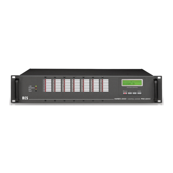
- Page 5 SYSTEM OVERVIEW The Control-Center: PSS-224 C Die Steuerzentrale: VARES-3000 PSS-224 C CONTROL-CENTER System-components regarding usage as System-components regarding usage as »DIGITAL CALL SYSTEM« »VOICE ALARMING SYSTEM« COMPLIANT TO DIN EN 50849 / IEC 50849 System-Komponenten bei Lösung als System-Komponenten bei Lösung als »DIGITALES RUFSYSTEM«...
- Page 6 PSS-244 C CONTROL-CENTER PMM-132D Message Module microSD-Card MODEL NO.: PSS-224C VARES-3000 Control-Center RCS AUDIO-SYSTEMS GMBH REAR VIEW PSS-224 C RÜCKANSICHT 1. Empty Slots 1. Leerschächte 7 empty slots for mounting the relay cards PRC-008 A, Leerschächte zum Einbau von Relaiskarten PRC-008x,...
- Page 7 PSS-224 C PMM-132D Message Module CONTROL-CENTER microSD-Card MODEL NO.: PSS-224C RES-3000 Control-Center S AUDIO-SYSTEMS GMBH 1 2 3 4 7 8 9 BELEGUNG DER ANSCHLUSSSTECKER BUS CONNECTOR PINNING WITH BUS ASSIGNMENT MIT BUSBELEGUNG 1. PSU 1. PSU Anschluss für +24V Versorgungsspannung vom Schalt- Connector for +24V supply voltage from the switching netzteil (PSU-xxx/24) power supply (PSU-xxx/24)
- Page 8 PSS-244 C CONTROL-CENTER SETTING IN OPERATION INBETRIEBNAHME The basic device is delivered without any modules or relay- Das Grundgerät wird ohne Module oder Relaiskarten gelie- cards. In order to insert the different types of relay-cards or fert. Zum Einbau von ver-schiedenen Arten von Relaiskarten additional modules such as the chime-module, the cabinet oder Zusatzmodulen wie z.
- Page 9 PSS-224 C CONTROL-CENTER FRONTPANEL DISPLAYS DIE ANZEIGEN AN DER FRONTSEITE On the left side three LED’s can be spotted. The green LED An der linken Seite findet man drei Leuchtdioden. Die grüne indicates whether the main power is working. The red emer- LED zeigt an, ob die 24V Versorgungsspannung vorhanden gency LED lights up, when the main alarm is activated.
- Page 10 PEU-056 B EXTENSION UNIT REARVIEW PEU-056 B RÜCKANSICHT PEU-056 B 1. Empty slot 1. Leerschächte These are empty slots to build in further relay cards, i.e. Leerschächte zum Einbau von Relaiskarten PRC-008x, PRC-008x, PRC-108x, PRC-408x or PRC-508x PRC-108x, PRC-408x oder PRC-508x.
- Page 11 PPS-024 B PROGRAM SELECTOR FUNCTIONAL DESCRIPTION FUNKTIONSBESCHREIBUNG PPS-024 B 24 differently programmed background-music zones may Mit dem PPS-024 B lassen sich 24 verschieden program- be switched on and off manually with the PPS-024 B. Each mierte Hintergrundmusikzonen von Hand ein- oder aus- relay can be allocated individually to one button on the PPS- schalten.
- Page 12 PRC-508 A MATRIX RELAY-CARD PRC-508 A SETTING IN OPERATION INBETRIEBNAHME The relay cards mounting order must be followed precisely. Die Bestückungsreihenfolge der Relaiskarten ist zwingend You have to start with position 1 on the front panel from the aufsteigend mit „1“ beginnend, frontseitig von links nach left to the right side.
- Page 13 PRC-508 A MATRIX RELAY-CARD FEATURES OF THE DIGITAL MATRIX RELAY CARD MERKMALE DER DIGITAL-MATRIX-RELAISKARTE VARES Digital Line Relay Card, 8 lines, monitors, VARES-Digital-Linien-Relaiskarte, 8 Linien, überwacht, Built-in module for 8 pieces monitored 100V lines in Einbau-Modul für 8 Stück überwachte 100V-Linien in PSS-224C PSS-224C equipped with 8 closed relays, loadable with max.
- Page 14 PRC-SERIES RELAY CARD PRC-008C/308B PRC-408 B SETTING IN OPERATION INBETRIEBNAHME The relay cards mounting order must be followed precisely. Die Bestückungsreihenfolge der Relaiskarten ist zwingend You have to start with position 1 on the front panel from the aufsteigend mit „1“ beginnend, frontseitig von links nach left to the right side.
- Page 15 PRC-SERIES RELAY CARD 11. Fix it with the enclosed blind cover for cards and the 11. Mit der beiliegenden Kartenblende und den Linsenkopf- rounded head screw M3x6. schrauben M3x6 befestigen. 12. Insert possibly earlier removed relay cards again. 12. Evtl. vorher entfernte darüberliegende Relaiskarten wie- der einsetzen.
- Page 16 PAX-404 A AUDIOMODULE SETTING IN OPERATION INBETRIEBNAHME The PAX-404 A enables you to Die PAX-404 A ermöglicht vier allocate four different inputs to verschiedene Eingänge auf vier four different outputs. verschiedene Ausgän-ge Zuzu- ordnen. Prior to using the PAX-404 A, the module has to be registered Vor Benutzung der PAX-404 A muss das Modul auf der Kon- on the configuration site ConfigV3000 in order to send it to figurationsseite in ProLi-neConfig eingetragen und zur PSS-...
- Page 17 PCM-100 C CHIME AND ALARM MODULE SETTING IN OPERATION INBETRIEBNAHME The PCM-110 C module generates an Das Modul PCM-100 C erzeugt einen alarm signal according to the DIN 33404 Alarmton nach DIN 33404 sowie 7 ver- as well as 7 different chime sounds. It is schiedene Gongarten.
- Page 18 PIC-208 B INPUT MODULE SETTING IN OPERATION INBETRIEBNAHME The PIC-208 B enables 8 diffe- Das PIC-208 B ermöglicht acht rent allocations of the program- verschiedene Zuordnungen pro- med line states including the grammierter Linienzu-stände chime selection, provided that a incl. Gongauswahl, sofern ein chime module is installed and registered.
- Page 19 PIC-208 B INPUT MODULE UTILIZATION AS NORMAL INPUT NUTZUNG ALS NORMALEINGANG The input with the lowest number has the highest priority Der Eingang mit der niedrigsten Nummer hat bei Nutzung als when used as a normal input within the inputs of the same Normaleingang die höchste Priorität innerhalb der Eingänge type.
- Page 20 PMM-132 D TEXT- & SIGNAL MEMORY SETTING IN OPERATION INBETRIEBNAHME SD-CARD The text module PMM-132 D re- Das Textmodul PMM-132 D er- plays alert signals and text mes- möglicht das Abspielen von sages in different zones. The Aufmerksamkeitssignalen module is used additionally as Textnachrichten in verschiedene a signal generator for different monitoring functions of the Zonen.
- Page 21 PMM-132 D TEXT- & SIGNAL MEMORY TABLE OF CONTENT SD-KARTE INHALTSVERZEICHNIS SD-KARTE (DEFAULT SETTINGS) (WERKSEINSTELLUNGEN) Filename Content Duration Name Dateiname Inhalt Dauer Name in ConfigV3000 im ConfigV3000 00.mp3 Sine wave 20Hz -6dB 20Hz 00.mp3 Sinuston 20Hz -6dB 20Hz 01.mp3 Sine wave 25Hz -6dB 25Hz 01.mp3 Sinuston 25Hz -6dB...
- Page 22 PMM-132 D TEXT- & SIGNAL MEMORY ADD CUSTOM TEXTS INDIVIDUELLE TEXTE HINZUFÜGEN Please regard the following: Hierbei ist folgendes zu beachten: 1. Prior to removing the SD-cart, please turn off the text 1. Vor Ausbau der SD-Karte Textmodul abschalten (Ausbau module (removal of SD-cart under voltage may cause da- der SD-Karte unter Spannung kann zur Beschädigung mage to the card or to the module!) An activated text mo-...
- Page 23 PLC-400x displays Das PLC-400x ermöglicht das system information such Anzeigen von Systeminformati- RCS VARES 3000 system-time, errors, etc. Using onen wie z.B. Systemzeit, Feh- SYSTEM: OK the 4 buttons you may maneuver lern, usw. Mittels der 4 Tasten through system-menu.
- Page 24 PMO-350 C MEASURING/MONITOR-MODULE MEASURING AND MONITORING MESS- UND ÜBERWACHUNGS- MODULE MODUL with microcontroller and integrated - mit Mikrocontroller und integrierter CPU - mit 8 K Bytes Flash program memory with 8K bytes flash program memory - mit 512 Bytes EEPROM with 512 bytes EEPROM - mit 1 KByte SRAM with 1 Kbyte SRAM...
- Page 25 PTM-101X/201X ALL CALL MIC OPERATING ELEMENTS BEDIENELEMENTE 1. Push the talk button 1. Talk-Taste Through pressing this button and keeping it pressed, the Durch Drücken und halten dieser Taste werden die vor- pre-selected relay-groups are activated and the micro- gewählten Relaisgrup-pen aktiviert und das Mikrofonsi- phone signal is interconnected.
- Page 26 PRM-108 B/PDM-208 B REMOTE MIC OPERATING ELEMENTS PRM-108 B/PDM-208 B BEDIENELEMENTE PRM-108 B/PDM-208 B 1. Group and function buttons 1. Gruppen- und Funktionstasten By pressing these buttons relay groups are chosen or Durch Drücken dieser Tasten werden Relaisgruppen aus- direct relay functions are activated.
- Page 27 PRM-108 B/PDM-208 B REMOTE MIC SETTING IN OPERATION INBETRIEBNAHME This remote microphone is connected to the BUS with the Die Sprechstelle wird über das Sprechstellenkabel PMC-xxx PMC-xxx desktop microphone cable. Power supply is car- mit dem Bus verbunden. Über das Sprechstellenkabel er- ried out through the remote microphone cable.
- Page 28 PEM-008B MIC EXTENSION UNIT PEM-008 SETTING IN OPERATION INBETRIEBNAHME Up to 7 pieces PEM-008B can be connected to one remote An eine Sprechstelle können bis zu 7 Stück PEM-008B an- microphone. Thereby it is important to pay attention to the gebaut werden.
- Page 29 PEM-008B MIC EXTENSION UNIT 13. Program module address: 13. Programmierung der Moduladresse a) Mount extension module to PDM-208 B and connect a) Erweiterungsmodul an PDM-208 B montieren und mit to bus cable. Ensure that the bus cable is connected Buskabel verbinden, dabei auf korrekten Anschluss correctly.
- Page 30 PZM-310 B TEN KEYS PAD FUNCTIONAL DESCRIPTION FUNKTIONSBESCHREIBUNG With the ten keys pad programmed individual lines and Mit der Zehnertastatur lassen sich vorher programmierte ein- groups can be selected before. In ConfigV3000 a code up zelne Linien und Grup-pen anwählen. In ConfigV3000 kann to with 3 digits for each line can be deposited from 1 to 999 ein bis zu 3-stelliger Code von 1 bis 999 (z.B.
- Page 31 PZM-310 B TEN KEYS PAD PZM-310B INSTALLATION OF THE PZM-310 B EINBAU EINES PZM-310 B The following work procedures are to be accomplished: Bei der Montage des Moduls ist folgende Vorgehensweise angebracht: 1. Substation PDM-208 B from the external bus take off 1.
- Page 32 PSM-108 B MIC FAULT INDICATOR PSM-108 B SETTING IN OPERATION INBETRIEBNAHME You can add a PSM-108x to a remote microphone. It is not An eine Sprechstelle kann ein PSM-108x angebaut werden. necessary to regard the internal settings of the BUS-address, Eine Einstellung der in-ternen Bus-Adressen ist nicht zu be- because the module has a fixed address.
- Page 33 PMO-400 B MICROPHONE MONITORING PMO-400 B SETTING IN OPERATION INBETRIEBNAHME With this module the acoustic noise of the remote micro- Das Modul ermöglicht in Verbindung mit dem Modul PMO- phones PRM-108 B or PDM-208 B can be monitored in 200x bzw. PMO-350 C eine Schallüberwachung der Sprech- connection with the module PMO-200x and PMO-350 C.
- Page 34 PFM-308 C FIRE BRIGADE REMOTE MIC OPERATING ELEMENTS PFM-308 C BEDIENELEMENTE PFM-308 C 1. Group and function buttons 1. Gruppen- und Funktionstasten By pressing these buttons relay groups are chosen or Durch Drücken dieser Tasten werden Relaisgruppen aus- direct relay functions are activated.
- Page 35 PFM-308 C FIRE BRIGADE REMOTE MIC This remote microphone has highest priority within the VARES Die Sprechstelle hat im VARES-System oberste Priorität system contrary to all other connected devices. If there are gegenüber allen anderen angeschlossenen Geräten. Wenn more than one fire brigade remote microphone within the sy- sich im System mehrere Notfall-/Feuerwehrsprechstellen stem, the one remote microphone with the lowest address befinden, so hat die Sprechstelle mit der kleinsten Adresse...
- Page 36 PFM-330 D FIRE BRIGADE WALL MIC OPERATING ELEMENTS PFM-330 D BEDIENELEMENTE PFM-330 B 1. Group- and control keys 1. Gruppen- und Funktionstasten When pressing this button, relay groups are selected or Durch Drücken dieser Tasten werden Relaisgruppen aus- one relay function is activated directly.
- Page 37 PFM-330 D FIRE BRIGADE WALL MIC SETTING IN OPERATION INBETRIEBNAHME This remote microphone is connected to the remote micro- Die Sprechstelle wird über einen festen Anschluss mit dem phone BUS through a fixed connector. Power supply is car- Sprechstellen-BUS ver-bunden. Über das Sprechstellenka- ried out through remote microphone cable.
- Page 38 PFM-330 D FIRE BRIGADE WALL MIC PIN ASSIGNMENT PIN BELEGUNG Assignment Belegung Audio Hot Audio Hot Audio Cold Audio Cold Shield / GND Shield / GND RS-485 A RS-485 A RS-485 B RS-485 B Busy Busy +24V +24V Technical data PFM-330 D Technische Daten PFM-330 D...
- Page 39 SOFTWARE CONFIGV3000 (V2) CONFIGV3000 SOFTWARE (V2) FOR WINDOWS...
- Page 40 SOFTWARE CONFIGV3000 (V2) SETTING IN OPERATION INBETRIEBNAHME Before installing ConfigV3000 software the Configuration Vor der Installation der ConfigV3000-Software muss der Program Adaptor PCA-500 has to be installed: Configuration Program Adaptor PCA-500 installiert werden: 1. Plug in the USB connector into the USB port on the 1.
- Page 41 SOFTWARE CONFIGV3000 (V2) Connect the PCA-500 to one bus socket or to one bus Verbinden Sie den PCA-500 mit einer Bus-Anschlussdose connector. To the bus at least one PSS-224A/B and oder der Bus-Anschlussbuchse. Am Bus sollten mindestens one remote microphone have to be connected. ein PSS-224A/B und eine Sprechstelle angeschlossen sein.
- Page 42 SOFTWARE CONFIGV3000 (V2) PROJECT/DEVICE OVERVIEW PROJEKT-/GERÄTEÜBERSICHT After the PSS-224 Configuration window is closed, a new Nachdem das VARES Konfigurations-Fenster geschlossen window appears. It shows the actual project file. Here all wurde, wird ein neues Fenster sichtbar: Es zeigt die aktuelle identified devices are listed.
- Page 43 SOFTWARE CONFIGV3000 (V2) microphones. Durch Anklicken des Buttons „ALARM“ öffnet sich ein wei- teres Fenster. Markieren Sie hier die Relais, die beim Wählen Clicking on button “Emergency” opens another window. Mark der Alarmtaste anziehen sollen. here all relays you want to be activated when the “ALARM” tact switch is activated on the remote microphones.
- Page 44 SOFTWARE CONFIGV3000 (V2) After all markings are done and confirmed with “O.K.”, the Nachdem alle Markierungen vorgenommen sind und mit window Speaker Line Programming opens again. „O.K.“ bestätigt sind, landet man wieder im Fenster Laut- sprecherlinien-Programmierung. Click here on “Send” for transmitting all settings to Klicken Sie jetzt auf „Senden“...
- Page 45 SOFTWARE CONFIGV3000 (V2) Clicking on tact switch buttons of the different blocks will Durch Anklicken der Tasten der einzelnen Tastenblöcke ge- open another new window. langt man in ein neues Fenster. Mark here all relays you want to be activated when the tact Markieren Sie hier die Relais, die beim Wählen der ersten switch of this block is activated on the remote microphones.
- Page 46 SOFTWARE CONFIGV3000 (V2) Ist keine Taste an der Sprechstelle aktiviert wird Hauptalarm ausgelöst. Achtung: This function is meant only for responsible personnel, since Achtung: the alarm is spent during faulty operation only over a line, Diese Funktion ist nur für zuständiges Personal gedacht, da instead of the complete building.
- Page 47 SOFTWARE CONFIGV3000 (V2) First select in the window „equipment“ PSS-224A/B. After- Zuerst wählt man im Feld „Gerät“ PSS-224A/B aus. Danach wards one receives the data through presses the buttons empfängt man die Daten durch drücken des Buttons „Emp- „receiving “. Here the current attitudes appear, the firmware fangen“.
- Page 48 SOFTWARE CONFIGV3000 (V2) ADDITIONAL FUNCTIONS ZUSÄTZLICHE FUNKTIONEN There are some buttons and menus we have not talked about Es gibt noch ein paar Buttons und Menüs, die noch nicht yet. Here is a short description: erwähnt worden sind. Hier eine kurze Beschreibung: •...
- Page 49 2.06f. PonyProg2000, ConfigV3000 und die dates on the provided CD-Rom or on our homepage www. neuesten Updates finden Sie auf der mitgelieferten CD-Rom rcs-audio.com as well as amongst the retail section. oder auf unserer Homepage: www.rcs-audio.com sowie im Händlerbereich unter VARES Hilfe.
- Page 50 SOFTWARE CONFIGV3000 (V2) FIRMWARE-UPDATE MIT PONYPROG2000 FIRMWARE-UPDATE MIT PONYPROG2000 AB VERSION 2.06F BETA AB VERSION 2.06F BETA: • Connect the programming adapter to your computer • Programmieradapter am PC anschließen • Start your computer • PC hochfahren • Start PonyProg (previous installation of this program is •...
- Page 51 NOTES...
- Page 52 Hardware and Software specifications subject to change without notice. Techische Änderungen in Hardware und Software vorbehalten. © Copyright by RCS AUDIO-SYSTEMS GmbH. RCS09.04.2018 Publication and duplication of the contained data only allowed with our strict permission. Veröffentlichung und Vervielfältigung der enthaltenen Daten, auch auszugsweise, nur mit unserer ausdrücklichen Genehmigung.
Need help?
Do you have a question about the PSS-224C and is the answer not in the manual?
Questions and answers