Table of Contents
Advertisement
Quick Links
Service Manual
Specifications
Information in brackets [ ] refers to model 47"
Power Source:
Rated Power Consumption:
Stand-by Power Consumption: 0.20W
Aerial Impedance:
Receiving System:
220-240V AC, 50 / 60Hz
119W [132W]
75 unbalanced, Coaxial Type
WT50B ( UK )
DVB-T / T2
Digital terrestrial services
DVB-S/S2
Freesat services via Satellite dish input
Receiver frequency range – 950 MHz to 2,150MHz
LNB Power and Polarisation – Vertical: +13V
22 kHz Tone – Frequency: 22kHz ± 2kHz
Symbol Rate – Max. 30MS/s
FEC Mode – 1/2, 3/5, 2/3, 3/4, 4/5, 5/6, 8/9, 9/10
Demodulation – QPSK, 8PSK
Not available for DiSEqC control
PAL I
UHF E21-E68
PAL 525/60
(AV only)
M.NTSC
(AV only)
NTSC
(AV only)
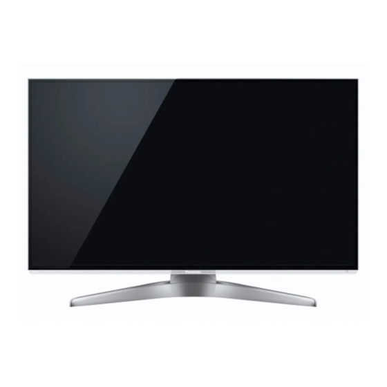
LCD Television
TX-L42WT50B
TX-L47WT50B
TX-L47WT50Y
TX-LR47WT50
LA34 Chassis
(MPEG2 and MPEG4-AVC(H.264))
Horizontal: +18V
Current: Max. 500mA (overload protection)
Amplitude: 0.6V ± 0.2V
© Panasonic Corporation 2012.
Unauthorized copying and
distribution is a violation of law.
ORDER No. PCZ1204084CE
REVISION 2
Advertisement
Table of Contents

Summarization of Contents
Safety Precautions
General Servicing Guidelines
Essential rules for safe servicing and customer return procedures.
Touch Current Measurement
Procedure and limits for verifying touch current safety.
Lead-Free Solder Information
Suggested Pb-Free Solder Types
Recommendations for suitable lead-free solder alloys for repairs.
Service Hints
Backcover Removal Procedure
Step-by-step instructions for removing the TV's backcover.
Pedestal Assembly Removal
Guide for detaching the TV's pedestal stand assembly.
Chassis Board Layout
Lead Wiring Location Guide
Diagram showing the location and routing of internal wiring.
Technical Description
Key Specifications for Digital Features
Details on software keys for CI Plus, DTCP-IP, Widevine, and Netflix.
USB HDD Recording Functionality
Explanation of how to record TV programs using a USB hard drive.
Setting Inspection
Voltage Confirmation Points
Test points and expected voltage values for A-board verification.
Service Mode Functionality
Entering Service Mode
Instructions on how to access the TV's hidden service menu.
Service Tool Mode
Accessing Service Tool Mode
Steps to enter and utilize the service tool mode.
SOS History and Power Status
Information on SOS history display and power on/off counts.
Hotel Mode Setup
Hotel Mode Purpose and Access
Explanation of hotel mode functionality and how to activate it.
Hotel Mode Menu Options
Details on configurable settings within the hotel mode menu.
SD Card Data Copy
Data Copy Purpose and Preparation
Instructions for preparing an SD card and copying TV data.
TV to SD Card Data Transfer
Procedure for copying TV settings and data onto an SD card.
SD Card to TV Data Transfer
Procedure for loading data from an SD card back to the TV.
Adjustment Methods
Contrast and White Balance Adjustment
Procedure for adjusting contrast and white balance settings.
Replacement Parts List
Important Safety Component Notice
Identification of safety-critical components requiring specific replacement parts.
Retention Time Limited (RTL) Parts
Information on parts with limited availability after production discontinuation.
Schematic Diagram Notes
Schematic Diagram Safety and Notes
Important safety remarks and general notes for interpreting schematic diagrams.
A-Board Conductor Views
A-BOARD TNPH0994 - Top Layer
Top side view of the A-board's conductor traces.
A-BOARD TNPH0994 - Bottom Layer
Bottom side view of the A-board's conductor traces.
LD-Board Conductor Views
LD-Board TNPA5615 - Top Layer
Top side view of the LD-board's conductor traces.
LD-Board TNPA5615 - Bottom Layer
Bottom side view of the LD-board's conductor traces.
LP-Board Conductor Views
LP-Board TNPA5645 - Top Layer
Top side view of the LP-board's conductor traces.
LP-Board TNPA5645 - Bottom Layer
Bottom side view of the LP-board's conductor traces.
K-Board Conductor Views
K-Board TNPA5605 - Top Layer
Top side view of the K-board's conductor traces.
K-Board TNPA5605 - Bottom Layer
Bottom side view of the K-board's conductor traces.


Need help?
Do you have a question about the TX-LR47WT50 and is the answer not in the manual?
Questions and answers