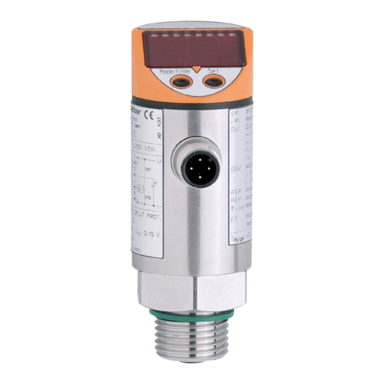
Summarization of Contents
Programming Operation
Selecting Parameters
Guides the user through selecting parameters for adjustment.
Setting Parameter Values
Explains how to adjust parameter values using the Set button.
Confirming Parameter Values
Describes the process of confirming the newly set parameter values.
Controls and Visual Indication
LED Indicators
Describes the green and yellow LEDs and their respective functions.
Display Unit
Details the 4-digit alphanumeric display for system temperature and parameter values.
Control Buttons
Explains the function of the Set and Mode/Enter buttons for operation.
Functions and Features
Core Unit Functions
Explains temperature detection, display, and dual output signal generation.
Connectable Temperature Sensors
Lists the types of temperature sensors (TS, TT, RTD) compatible with the unit.
Operating Modes
Details the 'Run mode' as the normal operating state of the unit.
Electrical Connection
Two-Wire Sensor Connection
Details the wiring for two-wire sensors and error correction in the COF menu.
Three-Wire Sensor Connection
Explains three-wire sensor wiring, menu settings, and cable resistance limits.
Four-Wire Sensor Connection
Specifies the wiring configuration for four-wire sensors using the Mmod setting.
Programming Details
Display Unit Selection
Emphasizes selecting the display unit (Uni) before setting parameters.
Parameter Locking Mechanism
Explains how to electronically lock/unlock parameters to prevent unwanted adjustments.
Installation and Set-up / Operation
Failure Indication
Lists and explains error codes (OL, UL, SCI, Err) for unit malfunctions.
Analogue Output Response
Describes how the analogue output signal behaves based on measuring range limits.
Technical Information / Functioning / Parameters
Adjustable Parameters Overview
Details adjustable parameters like SP1, rP1, OU1, OU2, ASP, and AEP with their settings.
Parameter Settings and Functions
Measurement Procedure Setting (Mmod)
Explains the Mmod setting for selecting 3-wire or 4-wire measurement.
Enhanced Functions Menu (EF)
Introduces the EF menu for accessing additional parameters via the SET button.
Min-Max Memory for System Temperature
Describes HI/LO functions to display max/min temperatures and how to erase memory.
Calibration Offset (COF)
Explains the COF parameter for offsetting the internal measured value against the real value.
Calibration Reset (CAr)
Details how to reset calibration settings using the CAr parameter.
Delay Time for Switching Output (dS1, dr1)
Explains delay times for switching output status changes (on/off delay).
Fault Response and Display Settings
Switching Output Fault Response (FOU1)
Defines how the switching output behaves during sensor faults (ON or OFF).
Analogue Output Fault Response (FOU2)
Determines analogue output behavior during sensor faults (specific mA/V values).
Output Polarity Setting (P-n)
Allows selection between positive (PnP) and negative (nPn) switching output polarity.
Display Update Interval (d1-d3, OFF)
Configures the update speed of the measured value on the display.
Display Unit Selection (Uni)
Explains the selection of display units (°C or °F) for measured and parameter values.
Operating Functions Explained
Hysteresis Function
Explains how hysteresis stabilizes switching states by defining switch-on and switch-off points.
Window Function
Describes the window function for monitoring a defined acceptable temperature range.
Analogue Output Scaling
Details scaling the analogue output using ASP (lower end) and AEP (upper end) parameters.
Output Signal Behavior
Voltage Output (0-10V)
Illustrates voltage output behavior in factory setting and scaled measuring range.
Current Output (4-20mA)
Illustrates current output behavior in factory setting and scaled measuring range.
Technical Data
Electrical Specifications
Provides operating voltage, current consumption, and sensor current data.
Performance Specifications
Details accuracy, resolution, and temperature drift for switching and analog outputs.
Environmental and Protection Ratings
Lists housing material, operating/storage temperatures, IP rating, and EMC compliance.


Need help?
Do you have a question about the TR2432 and is the answer not in the manual?
Questions and answers