
Related Manuals for Apollo Valves RPLF4A


Summary of Contents for Apollo Valves RPLF4A
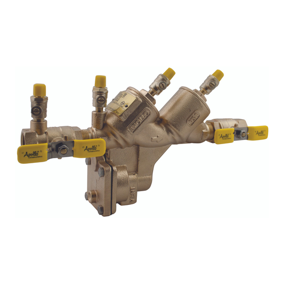
- Page 1 BFMM RP4A SBF 1-2012 1/2” - 2” Model RP4A Reduced Pressure Principle (RP) Back ow Preventer Model RPLF4A...
-
Page 2: Table Of Contents
INSTALLATION, OPERATION, & MAINTENANCE MANUAL TABLE OF CONTENTS Reduced Pressure Principle Back ow Preventer 1/2” – 2” Section Page Description and Operation ..............3 Installation . -
Page 3: Reduced Pressure Principle Back Ow Preventer 1/2
BFMM RP4A SBF REDUCED PRESSURE PRINCIPLE BACKFLOW PREVENTER 1/2” 2” I. DESCRIPTION AND OPERATION The Reduced Pressure Principle (RP) device consists of two independently-acting, spring-loaded check valves, together with a hydraulically dependent, mechanically independent pressure di erential relief valve, located in the zone between the check valves. - Page 4 INSTALLATION, OPERATION, & MAINTENANCE MANUAL Figure 1 FLOWING CONDITION Figure 2 NO FLOW CONDITION NOTE: Pressures shown are for illustrative purposes only and are not necessarily indicative of any actual valve. Customer Service (704) 841-6000 www.apollovalves.com...
-
Page 5: Trouble Shooting Guide
BFMM RP4A SBF III. TROUBLE SHOOTING SYMPTOM CAUSE CORRECTIVE ACTION Relief valve continuously #1 check valve fouled with debris. Inspect and clean seat disc and discharges during no- ow seat condition. b. #2 check valve fouled with b. Inspect and clean seat disc and debris coupled with a seat. -
Page 6: Maintenance Instructions
INSTALLATION, OPERATION, & MAINTENANCE MANUAL IV. MAINTENANCE INSTRUCTIONS 1/2” – 2” A. Disassembly - Check Valves Close #2 shut-o valve, then close #1 shut-o valve. Bleed pressure from the assembly by opening #2, #3, and #4 test cocks. Unscrew cap using hex head provided. Push down and turn the spring retainer 90 degrees to remove. -
Page 7: Testing Procedures
BFMM RP4A SBF Assembly - Relief Valve Apply a thin coat of Apollo lubricant, DOW® 111 or equal on o-rings before installing. Install o-ring on RV seat. Line up the seat with the bore and push rmly into place. If the RV stem has been disassembled, install o-ring onto RV stem. - Page 8 INSTALLATION, OPERATION, & MAINTENANCE MANUAL TEST NO. 3 PURPOSE: To test check valve #1 for tightness. Close high “A” valve and open test cock #2. Close test cock #4. Open low valve “B”, this will bleed air from low side of gauge, then closing valve “B” restores the system to a normal static condition.
- Page 9 BFMM RP4A SBF Figure 3 Customer Service (704) 841-6000 www.apollovalves.com...
-
Page 10: Parts List
INSTALLATION, OPERATION, & MAINTENANCE MANUAL PARTS LIST 1/2” - 2” Figure 4 Customer Service (704) 841-6000 www.apollovalves.com... - Page 11 BFMM RP4A SBF RP4A and RPLF4A Parts List Part Number Std. or Item # Description Qty. 1/2” 3/4” 1” 1-1/4” 1-1/2” 2” Body Consult Factory Label Plate Consult Factory Label Plate Tacks I-2614-00 Test Cock M x F (81 metal)
- Page 12 INSTALLATION, OPERATION, & MAINTENANCE MANUAL Inlet and Outlet Shut-O Valves Part Number Std. or Item # Description Qty. 1/2” 3/4” 1” 1-1/4” 1-1/2” 2” 81 Mtl 77B-103-85 77B-104-83 77B-105-83 T2 Inlet NPT Ball Valve w/ “T” Not Available Handle (Standard) 77BLF-103-85 77BLF-104-83 77BLF-105-83...
-
Page 13: Repair Kits (1/2"- 2" )
BFMM RP4A SBF REPAIR KITS RP4A & RPLF4A 1/2” 2” Size Check Module Rubber Kit (One kit repairs one check) (Universal, for standard & lead free valves) 1/2” 3/4” 1” 1-1/4” – 1-1/2” 2” RK4A12CMR RK4A34CMR RK4A1CMR RK4A112CMR RK4A2CMR Repair Kit Model Number... - Page 14 INSTALLATION, OPERATION, & MAINTENANCE MANUAL Repair Kits RP4A & RPLF4A 1/2” – 2” (continued) Size RP Relief Valve Complete Kit (Universal, for standard & lead free valves) 1/2” 3/4” 1” 1-1/4” – 1-1/2” 2” Repair Kit Model Number RK4A1RVC RK4A112RVC RK4A2RVC Item # Ordering Number...
- Page 15 BFMM RP4A SBF Customer Service (704) 841-6000 www.apollovalves.com...
- Page 16 SALES & CUSTOMER SERVICE: Phone: (704) 841-6000 Fax: (704) 841-6020 www.apollovalves.com AGENCY AREAS COVERED EMAIL PHONE Mid South Marketing, Inc. VA/MD/Washington, D.C./WV-East midsouth7@aol.com 804-213-3801 804-213-3802 Pro Marketing, Inc. NC/SC/TN-East sales@promarketinginc.net 864-578-4334 864-578-4889 Spirit Group FL (except Panhandle) info@spiritgroupinc.com 407-291-6035 407-299-0378 Tim Morales &...
Need help?
Do you have a question about the RPLF4A and is the answer not in the manual?
Questions and answers