Table of Contents
Advertisement
Quick Links
Advertisement
Table of Contents

Related Manuals for ABL METERL

Summary of Contents for ABL METERL
- Page 1 METERS METERL Installation and Configuration Guide Article No.: 0301676_EN_a...
- Page 2 Contact Contact ABL GmbH Albert-Büttner-Straße 11 91207 Lauf an der Pegnitz Germany +49 (0) 9123 188-0 +49 (0) 9123 188-188 info@abl.de www.ablmobility.de Customer Service +49 (0) 9123 188-0 service@abl.de www.ablmobility.de/en/service/support/ Revision: 0301676_EN_a, Version: 23.05.22...
-
Page 3: Table Of Contents
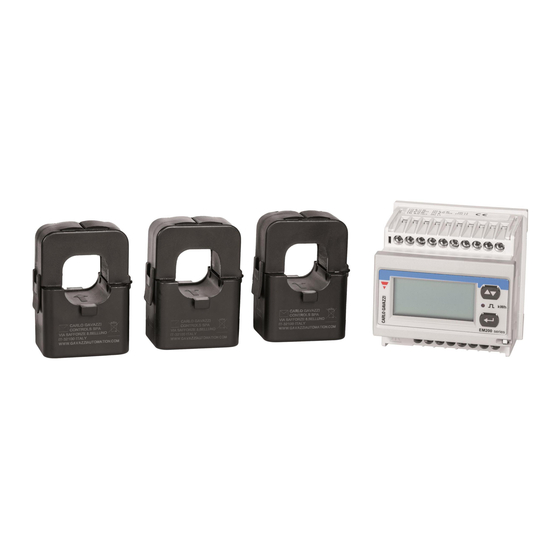
User information Dimensional drawings and dimensions Energy meter EM210 Cable type current transformers up to 300 A Cable type current transformers up to 600 A Introduction to the METERS and METERL load management systems Identification Items supplied Compatible products The energy meter at a glance... -
Page 4: Additional Technical Information
This document describes how to install the three cable type current transformers and the energy meter as well as how to subsequently configure them on the energy meter and via the ABL User Interface software. It is recommended that all working steps described in this document are carried out by qualified specialist electrical contractors only. -
Page 5: Important Information
ƒ Please read this manual carefully. ƒ Heed all warnings and follow all instructions. ƒ Only use components intended and sold for the product by ABL. ƒ Do not install this device in close vicinity to running water, water jets or areas subject to flooding. -
Page 6: User Information
Important information ƒ Electrical installation and testing must be carried out with reference to local rules by a qualified specialist electrical contractor, who, on the basis of their specialist training and experience, as well as their knowledge of the relevant standards, is able to assess and carry out the working steps described in this manual and recognise potential hazards. -
Page 7: Dimensional Drawings And Dimensions
Dimensional drawings and dimensions Dimensional drawings and dimensions The following dimensional drawings show the dimensions of all components of the METERS and METERL load man- agement systems. Energy meter EM210 Energy meter (included in METERS and METERL), front and side view (all dimensions in mm) Cable type current transformers up to 300 A... -
Page 8: Introduction To The Meters And Meterl Load Management Systems
(eMH2 | eMH3 | eMC2 | eMC3) or control unit (1V0001 | 1V0002) in a group or individual installation and allows dy- namic and efficient distribution of the available electricity to all charge points based on this measurement. METERS can measure currents up to 300 A, while METERL is designed for larger installations with up to 600 A. - Page 9 = 492 mm, w = 394 mm, d = 192 mm (Housing without protrusions) ƒ Charging pole eMC2 Controller (2P4445) Charging pole from ABL for use as a controller in a group installation with two charging sockets h = 1,460 mm, w = 440 mm, d = 200 mm (Housing without protrusions) ƒ...
-
Page 10: The Energy Meter At A Glance
You can find further information on key operation in section “Setting up the energy meter” on page 19. Output and RS485 terminals The static outputs " to % are not used with METERS | METERL. The screw terminals & to ) serve as RS485 interfaces for communication with the controller charging station/control unit. The screw terminal ~ is required for terminating the RS485 bus. -
Page 11: The Display At A Glance
D. The cable type current transformer at a glance METERS | METERL are supplied with three cable type current transformers each, which are designed for measuring currents up to 300 A (METERS) or 600 A (METERL), but are otherwise identical in construction. - Page 12 Introduction to the METERS and METERL load management systems Energy flow arrows These arrows on the housing specify the energy flow and thus the installation direction. Connection cables The two cables are used to connect to the screw terminals 1 to 6 of the energy meter. The red wire K should be screwed into an odd-numbered terminal on the meter (1, 3 and 5), while the black wire L is as- signed to the even-numbered terminals (2, 4 and 6).
-
Page 13: Mechanical And Electrical Installation
Mechanical and electrical installation Mechanical and electrical installation The METERS and METERL load management systems can be used flexibly for the total current measurement of a sys- tem or for section current measurement within a system. Total current measurement For total current measurement, the cable type current transformers are installed on the individual phases of the house supply line and the energy meter on the house connection. -
Page 14: Selecting The Connection Mode
WARNING! Support for non-compatible connection modes The energy meter supplied with METERS | METERL supports other connection types in principle, although these are not required in practical use as a load management system. Therefore, always make sure that the energy me- ter is set to the appropriate connection option in the SYS menu. -
Page 15: Installation Of The Energy Meter And The Cable Type Current Transformers
Installation of the energy meter and the cable type current transformers Installation of the energy meter and the cable type current transformers The energy meter and the current transformers must be installed in a distribution box. Depending on the position of the current measurement, you will need to use the distributor for the house supply line (total current measurement) or the sub-distributor for the building (section current measurement). - Page 16 Mechanical and electrical installation Install the energy meter on a DIN rail in the distributor. y The distance to the current transformers is determined by the connection cables of the transformers. Locate the cables for current measurement in the distributor. Connect the energy meter to the mains via specially fused cable taps (F = 315 mA).
- Page 17 Installation of the energy meter and the cable type current transformers Connection mode 3P.n Cable type current transformer 1 – Cable type current transformer 2 – – Cable type current transformer 3 – Open a cable type current transformer, place it around one of the cables and close the catch, which must audibly click into place.
-
Page 18: Data Connection With The Controller Of A Group Installation
The Modbus interface depends on the year of manufacture – on older ABL charging sta- tions it is designed with spring terminals and on newer models it is equipped with RJ45 sockets. METERS | METERL are compatible with both systems. -
Page 19: Setting Up The Energy Meter
Setting up the energy meter NOTE Adhering to the colour scheme when wiring via the E2I interface In contrast to the wiring for charging stations with spring terminals, you must always adhere to the colour as- signment shown above for charging stations with an E2I interface! ƒ... - Page 20 Mechanical and electrical installation Proceed as follows to set up the energy meter: ≥3S Press and hold the enter key for about 3 seconds. y The password entry menu will be displayed. NOTE Enter the factory default password A password is required in order to set up the energy meter. This is set as 0 by default. If a value other than 0 is displayed, press the toggle ≥3S until 0 appears on the display and hold the...
- Page 21 Use the toggle key to select the appropriate ≤1S transformer ratio and hold the enter key about 3 seconds to confirm. y METERS: Select the value 60 y METERL: Select the value 120 ≥3S ≤1S Use the toggle key to select the Add menu for...
- Page 22 The energy meter is now set up for operation as a load management system for a group installation. The next step is to set up the individual charging stations and the group in the ABL Configuration Software and ABL User Inter-...
-
Page 23: Setup Via The Abl User Interface Application
Before you set up and commence initial operation of METERS | METERL, your charging system must first be correctly addressed and completely set up. METERS | METERL can then be set up for operation with the charging system via the ABL User Interface web-based application. - Page 24 Open a web browser on your computer and enter the following address: http://169.254.1.1:8300/. This opens the ABL User Interface online appli- cation, where you are automatically logged in with the Owner role. WARNING!
- Page 25 Setting up the energy meter Select the energy meter with the highest revision number. Enter the number 1 in the selection list at the bot- tom and click the Save button. y The external energy meter is then displayed next to the controller and the already selected extender charging stations in the Products >...
- Page 26 After you have set up all Extender charging stations and the external meter for the Controller, you must then de- fine the parameters for the entire system. To do so, proceed as follows: Make sure you are still logged into the ABL User In- terface application in the Installer role.
- Page 27 Setting up the energy meter NOTE Explanation of the fallback value If you are not sure which static maximum current the charging group should be limited to if the time limit (see be- low) is exceeded, enter the value 0 A here: This will cause all charging operations to be interrupted in the event of a fallback.
- Page 28 Setup via the ABL User Interface application Then click Perform reconfiguration to restart the system. Switch to the Overview > General tab: this shows at a glance whether your system is set up correctly. This completes the setup of the charging group and the charge management.
-
Page 29: Appendix
Technical specifications Appendix Technical specifications Model code METERS METERL Gross dimensions (H×W×D) 265 × 205 × 120 mm Weight (gross) 1.2 kg 1.6 kg Energy meter, 3 cable type current transformers (300 | 600 A), Items supplied download information Controller Wallbox eMH2 / eMH3 | Controller Charging Pole eMC2 / eMC3 Compatible product ranges external control unit 1V0001 / 1V0002 Energy meter Protection class front / screw... -
Page 30: Ip Rating
Appendix Model code METERS METERL Cable type current converter IP rating IP20 Operating temperature -20 to 65°C -20 to 50°C Ambient temperature (storage) -25 to 80°C Cable type current converter 65.5 × 46 × 35 mm 84 × 57 × 39 mm dimensions Secondary output UL R/C cable, 16 AWG (1.3 mm²) Cable diameter 24 mm... -
Page 31: Allocation Schematic From Spring Terminal To Easy2Install Interface
(L) of the next Extender charging station. In both cases, the individual wire strands of the Ethernet cable must be allocated as illustrated below. Spring terminal Energy meter RJ45 plug Top view of ABL bus Connection PIN allocation Top view of RJ45 plug terminal allocation... -
Page 32: Copyright And Disclaimer
Appendix Copyright and disclaimer Copyright © 2022 Version 0301676_EN_a, Version: 23.05.22 All rights reserved. ƒ Any information contained in this manual may be changed without prior notice and does not represent any obliga- tion on the part of the manufacturer. ƒ... - Page 33 Copyright and disclaimer...
- Page 34 ABL GmbH Albert-Büttner-Straße 11 91207 Lauf an der Pegnitz Germany +49 (0) 9123 188-0 +49 (0) 9123 188-188 info@abl.de www.ablmobility.de...
Need help?
Do you have a question about the METERL and is the answer not in the manual?
Questions and answers