Table of Contents

Related Manuals for ATO LW Series

Summary of Contents for ATO LW Series
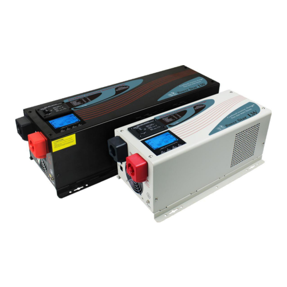
- Page 1 Read the full manual before using this product Pure Sine Wave 220-240V 50-60Hz Low Frequency Inverter User Manual For LK/LW series Power Star inverters only, models: LK2000, LK2000-24, LK3000, LK3000-24, LK3000-48, LK6000-24, LK6000-48...
-
Page 2: Safety Precautions
• Always switch on the inverter first, before plugging in any appliances. The product should be handled and installed by professionals or appropriately qualified persons. Suitable precautions and safety measures should be taken in all cases. Global Shipping sales@ato.com www.ato.com 18005851519... -
Page 3: Product Overview
AC output, the inverter exits the standby “sleep” mode immediately and starts supplying the full power again to the mains AC output. The load has to be in Global Shipping sales@ato.com www.ato.com 18005851519... -
Page 4: Installation And Wiring
Cable length 0-1.5m Cable length 1.5-4.0m LK2000-24 (2000W 24V), LK3000-48 (3000W 48V), 25mm 35mm LK3000-24 (3000W 24V), LK6000-48 (6000W 48V) 35mm 50mm LK2000 (2000W 12V) 50mm 70mm LK3000 (3000W 12V), LK6000-24 (6000W 24V) 70mm 90mm Global Shipping sales@ato.com www.ato.com 18005851519... -
Page 5: Power Out
The next step is wiring the AC output and AC input of the inverter. Keep the inverter switched off during this procedure. The overall connection scheme is provided below. Wiring AC input and output terminals of LK/LW Series Power Star inverters Output Input Power out Power in < < < < < < Global Shipping sales@ato.com www.ato.com 18005851519... - Page 6 Installing the remote On/Off control (can be purchased separately) If you have purchased a remote On/Off switch with 5m cable for your inverter, it can be plugged into the “Remote control” socket located on the battery terminals side of the inverter. Global Shipping sales@ato.com www.ato.com 18005851519...
-
Page 7: Operation Modes
The inverter main switch panel has a 3-position rocker switch and 3 LED lights: Switch: power saver auto position Battery charge LED indicator Inverter work LED indicator Alarm and fault LED indicator Switch: power saver off position Switch: unit off (middle) position Global Shipping sales@ato.com www.ato.com 18005851519... - Page 8 “>> 03”) as shown on the picture. The inverter will be ‘sleeping’ in standby until a load (>25W) is connected to the inverter output. The signs “OUTPUT” and “O/P” will be flashing on the screen. Global Shipping sales@ato.com www.ato.com 18005851519...
-
Page 9: Lcd Display
AC input frequency and voltage. The battery is charging Displays and alternates every 3 sec. Low battery warning, flashes once a between output frequency second voltage. Shows the battery capacity The inverter is working in the bypass mode Global Shipping sales@ato.com www.ato.com 18005851519... - Page 10 This setting is for the output frequency. Choose from AF (auto detection of frequency), 50Hz or 60Hz. The default value for the UK is 50Hz. If this parameter is set to AF, the inverter can detect the frequency from the mains AC input. Global Shipping sales@ato.com www.ato.com 18005851519...
- Page 11 When one of these limits is reached, the inverter shuts down automatically for protection. This function is designed to make sure the input voltage stays within the acceptable range and the risk of damage to your appliances is minimal. Global Shipping sales@ato.com www.ato.com 18005851519...
- Page 12 * The voltages are provided for 12V batteries. For 24V multiply by x2, for 48V multiply by x4. The desulphation cycle is marked in red because this is a very dangerous setting. Please see Appendix 2 for more information. Global Shipping sales@ato.com www.ato.com 18005851519...
- Page 13 Charger damage. Contact the manufacturer or supplier. Over charge Check if the battery bank voltage is appropriate for the inverter and reconfigure Battery over voltage the batteries if needed. Global Shipping sales@ato.com www.ato.com 18005851519...
-
Page 14: Specifications
10-15.7V for 12V (*2 for 24V, *4 for 48V) Over charge protection shutdown: 15.7V for 12V (*2 for 24V,*4 for 48V) Mechanical parameters 2000W and 3000W models: 460*220*190mm Size 6000W model: 650*220*190mm Weight 2000W 20kg, 3000W 25.5kg, 6000W 48kg. Global Shipping sales@ato.com www.ato.com 18005851519... -
Page 15: Appendix 1. Battery Charging Stages (When The Mains Battery Charger Is On)
If the AC is reconnected or the battery voltage drops below 12V DC, the charger will reset the cycle above. If the charger remains in the float stage for 10 days, the charger will reset the cycle. Global Shipping sales@ato.com www.ato.com 18005851519... -
Page 16: Appendix 2. Battery Desulfation Cycle
You may need to repeat the process a few times. This is a professional tool. Never leave the system unattended when using this mode. If the battery temperature reaches 50°C, or you come across any other irregularities, stop the process immediately. Global Shipping sales@ato.com www.ato.com 18005851519...
Need help?
Do you have a question about the LW Series and is the answer not in the manual?
Questions and answers