
Related Manuals for SIUI CTS-9009

Summarization of Contents
Chapter 1 System
1.1 Application Scope
Describes the intended uses and applications of the CTS-9006 flaw detector.
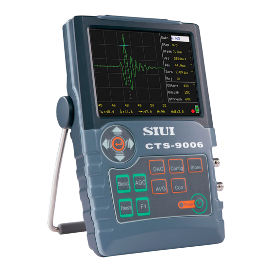
1.2 Appearance
Details the physical layout and components of the flaw detector's front panel.
Chapter 2 System Operation
2.1 Power Supply
Covers the power source and management for the ultrasonic flaw detector.
2.2 Power On
Instructions on how to turn on the digital ultrasonic flaw detector.
2.3 Power Off
Procedures for safely shutting down the ultrasonic flaw detector.
2.4 Main Menu Selection
Guidance on navigating and selecting options from the main menu interface.
2.5 Submenu Selection
Explains how to choose and access submenus for detailed settings.
2.6 Turning Page
Method for navigating through pages or screens within the system menus.
2.7 General Submenu Adjustment
Details on adjusting parameters within general submenus.
2.8 Extended Submenu
Information on accessing and using extended submenu options.
2.9 Self-Defined Function Key
Configuration and usage of the programmable function key.
2.10 Freeze
Function to freeze the current display for analysis.
2.11 Auto Gain
Automatic adjustment of signal gain for optimal display.
2.12 Auto Correction
Automatic correction features for signal processing.
2.13 Angle Measurement
Procedure for performing angular measurements using the device.
2.14 DAC
Functions related to the Distance Amplitude Correction (DAC) curve.
2.15 AVG
Functions related to the Amplitude versus Distance (AVG) curve.
2.16 Store
Features for saving, recalling, and managing test data and settings.
2.17 Coordinate Mode
Selection and configuration of coordinate systems for measurement.
2.18 Parameter Output
Process for exporting or outputting system parameters.
2.19 MeasPt Select
Selection of measurement points for data acquisition.
2.20 Measurement Select for Gate B
Choosing measurement types for Gate B.
Chapter 3 Prompts and Tips for System Application
3.1 Gain Step Quick Adjustment
Quick method for adjusting the gain in steps.
3.2 Quick Store and Recall
Efficiently saving and retrieving system states or parameters.
3.3 Test Range Setup
Configuration of the testing range parameters.
3.4 System Text Prompt
Understanding and utilizing system text prompts for guidance.
3.5 Store and Recall of System State and Testing Parameter
Saving and loading complete system states and test parameters.
3.6 System Parameter Setup Specific to Testing
Customizing system parameters for specific testing scenarios.
3.7 Using Battery to Increase Anti-interference
Tips for using battery power to minimize interference.
3.8 Application of PeakEnv
Utilizing the Peak Envelope feature for signal analysis.
3.9 Application of PeakEcho
Using the Peak Echo function for specific measurements.
3.10 Applying PeakEcho to Make DAC Curves
Method for creating DAC curves using Peak Echo.
3.11 Using Different Colors to Achieve Optimal Visual Effect in Application
Tips on using color settings for better visual representation.
3.12 Impact of Gate State on Gate Measurement Results
Understanding how gate settings affect measurement outcomes.
Chapter 4 Testing Application and Examples
4.1 Testing with a Normal Probe
Procedure for performing tests using a standard probe.
4.2 Testing with an Angle Probe
Methodology for conducting tests with an angle beam probe.
4.3 Application Examples
Demonstrations of the flaw detector in practical testing scenarios.
Chapter 5 Peripheral Devices, Ports and Accessories
5.1 Probe Ports
Details on the probe connectors and their functionality.
5.2 USB Port
Information on using the USB port for data transfer and connectivity.
5.3 Battery
Instructions on battery installation, charging, and maintenance.
5.4 Charger/Adaptor
Usage and handling guidelines for the device charger and adaptor.
Chapter 6 Training, System Maintenance and Service
6.1 Training
Information and resources for operator training.
6.2 System Maintenance
Guidelines for routine maintenance to ensure optimal performance.
6.3 Service
Information and procedures for obtaining technical service.
Appendix A Common Failures and Troubleshooting
A.1 The System Cannot Power On
Troubleshooting steps for power-on issues.
A.2 The System Cannot Power Off
Solutions for problems encountered when powering off the system.
A.3 No "USB Disk Connected" Prompt
Diagnosing why the system does not recognize a connected USB disk.
A.4 Cannot Print
Troubleshooting issues related to printing functionality.
A.5 Cannot Charge
Steps to resolve problems with battery charging.
A.6 No Echo
Diagnosing and resolving the absence of an echo signal.
A.7 Cannot Make DAC Curves
Troubleshooting difficulties in creating DAC curves.
A.8 Cannot Make AVG Curves
Solutions for issues encountered when creating AVG curves.
A.9 Incorrect Depth Reading with Angle Probe
Addressing inaccuracies in depth readings when using angle probes.
A.10 Incorrect Horizontal Reading with Angle Probe
Resolving errors in horizontal readings with angle probes.
Appendix D Additional Data on CTS-9009
D.1 Appearance
Details on the physical appearance of the CTS-9009 model.
D.2 CTS-9009 Menu Structure
Overview of the menu hierarchy specific to the CTS-9009.
D.3 Addition Functional Operation (Based on CTS-9006)
Explains additional functions and operations relevant to CTS-9009.
Need help?
Do you have a question about the CTS-9009 and is the answer not in the manual?
Questions and answers