Advertisement
Table of Contents
Advertisement
Table of Contents

Related Manuals for AUX ACHP-H08/4R3HA


Summary of Contents for AUX ACHP-H08/4R3HA
- Page 1 Split - Air to Water Heat Pump 20220105 Technical & Service Manual Split Air to Water Heat Pump ACHP-H04/4R3HA ACHP-H06/4R3HA ACHP-H08/4R3HB ACHP-H10/4R3HB ACHP-H08/4R3HA ACHP-H10/4R3HA ACHP-H12/5R3HA ACHP-H14/5R3HA ACHP-H16/5R3HA Version 2 2022-01-05...
-
Page 2: Table Of Contents
Split - Air to Water Heat Pump 20220105 Contents Part1 General information ................3 Part2 Features ....................7 Part3 Piping System ..................9 Part4 Dimension .................... 21 Part5 Electrical Principle Diagram ............... 24 Part6 Capacity Amendment ................26 Part7 Hydronic Performance ................ 42 Part8 Sound Levels .................. -
Page 3: Part1 General Information
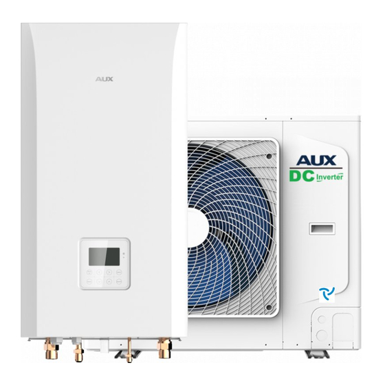
Split - Air to Water Heat Pump 20220105 Part1 General information 1. Nomenclature Outdoor Unit NOTE: 1、A: AUX 2、C:chiller 3、H: heat 4、P: pump 5、H: cooling and heating 6-7、capacity:04:4kW; 06:6kW; 08:8kW; 10:10kW; 12:12kW; 14:14kW; 16:16kW; 8、power supply:4:220V-240V-1-50Hz;5:380V-415V-3-50Hz 9-10、R3:R32 11、H:high efficiency 12、A: design number 13、O:outdoor unit... - Page 4 Split - Air to Water Heat Pump 20220105 2. Unit appearance Outdoor unit Hydronic box Capacity Appearance Model Model Appearance ACHP-H04/4R3HA-O ACHP-H04/4R3HA-I ACHP-H06/4R3HA-O ACHP-H06/4R3HA-I ACHP-H08/4R3HA-O ACHP-H08/5R3HA-I ACHP-H10/4R3HA-O 10kW ACHP-H10/5R3HA-I ACHP-H12/5R3HA-O 12kW ACHP-H12/5R3HA-I ACHP-H14/5R3HA-O 14kW ACHP-H14/5R3HA-I ACHP-H16/5R3HA-O 16kW ACHP-H16/5R3HA-I 3.Product line...
- Page 5 Split - Air to Water Heat Pump 20220105 3. Selection and System Design 3.1 Selection procedure Step1 Total heat load calculation Calculate conditioned surface area Select the heat emitters (type, quantity, water temperature and heat load) Step2 System configuration Decide whether to include AHS (auxiliary heat source) and set AHSs switching temperature Decide whether backup electric heater is enabled or disabled Step3 Selection of outdoor units Determine required total heat load on outdoor units.
- Page 6 UPMM25-95 Floor heating mixing water pump wilo Para25/9 DHW water pump wilo RS15/6 solar water pump wilo Para25/8 3.5 Match table of ODU and Hydronic Box Hydronic Box ACHP-H04/4R3HA-O AHM-P24R2/C9D3A ACHP-H06/4R3HA-O AHM-P24R2/C9D3A AHM-P24R2/C9D3A ACHP-H08/4R3HA-O AHM-P36R25/C9D9A AHM-P24R2/C9D3A ACHP-H10/4R3HA-O AHM-P36R25/C9D9A ACSHC-H42A5/ASR2DI AHM-P60R25/C9D9A...
-
Page 7: Part2 Features
Split - Air to Water Heat Pump 20220105 Part2 Features 1. Heating + Cooling +Demostic hot water 2. DC Inverter Technology, High Energy Efficient The compressor speed is controlled according to the indoor heating demand, and the output is completely on demand, more comfortable enjoyment: In any case, it can maintain a stable indoor temperature Full DC inverter system, inverter compressor + DC external fan + inverter water pump. - Page 8 Split - Air to Water Heat Pump 20220105 amend factor single connection pipe(m) 0.98 0.96 0.94 0.92 0.88 0.86 0.84 0.82 0.97 0.95 0.93 0.91 0.89 0.87 0.85 0.83 0.81 hydronic box above 0.94 0.92 0.88 0.86 0.84 0.82 the ODU 0.91 0.89 0.87...
-
Page 9: Part3 Piping System
Split - Air to Water Heat Pump 20220105 Part3 Piping System 1. Piping diagram 1.1 Outdoor Unit Defrost tem.Sensor Stop valve Ambient Tem.sensor Condensor High pressure sensor LP switch High pressure switch Suction tem.sensor Discharge tem.sensor COMP Stop valve Solenoid valve Capillary... - Page 10 Split - Air to Water Heat Pump 20220105 1.2 Hydronic Box Pressure gauge Plate heat exchanger(PHE) Gas pipe Temp.sensor Expansion tank Inverter water pump Liquid pipe Temp.sensor E-heater PHE outlet Temp.sensor PHE inlet Temp.senso Discharge valve Hydronic box outlet Temp.sensor Flow switch Safty valve Anti-freeze pressure switch...
- Page 11 Split - Air to Water Heat Pump 20220105 1.2 Air to water heat pump Tsolar Solar panel temp. sensor Temperature of domestic hot water tank Three-way valve Tici Plate heater liquid temp. sensor E-heater in hydronic box Tico Plate heater gas temp. sensor E-heater in tank Room temp.
- Page 12 Split - Air to Water Heat Pump 20220105 2. System Configurations R32 Split Type Air Source heat pump unit can be configured to run with the electric heater either enabled or disabled and can also be used in conjunction with an auxiliary heat source such as a boiler. The chosen configuration affects the size of heat pump that is required.
- Page 13 Split - Air to Water Heat Pump 20220105 3. Typical Applications 3.1 Space Heating Only The room thermostat is used as a switch. When there is a heating request from the room thermostat, the unit operates to achieve the target water temperature set on the Wired controller. When the room temperature reaches the thermostats set temperature, the unit stops.
- Page 14 Split - Air to Water Heat Pump 20220105 3.2 Space Heating and Domestic Hot Water The room thermostats also can connect to a motorized valve. Each rooms temperature is regulated by the motorized valve on its water circuit. Domestic hot water is supplied from the domestic hot water tank connected to the hydronic box.
- Page 15 Split - Air to Water Heat Pump 20220105 3.3 Space Heating, Space Cooling and Domestic Hot Water Floor heating loops & Heating radiator & Fan coil units are used for space heating , fan coil units are used for space cooling. Domestic hot water is supplied from the domestic hot water tank connected to the hydronic box.
- Page 16 Split - Air to Water Heat Pump 20220105 3.4 Space Heating and Space Cooling Floor heating loops & Heating radiator & fan coil units are used for space heating , fan coil units are used for space cooling. In space cooling mode, the 2way valve is closed to prevent cold water entering the floor heating loops &...
- Page 17 Split - Air to Water Heat Pump 20220105 Auxiliary heat source provides space heating only Users can also use only gas water heaters for heating REMARK Outdoor unit Mixing valve and mixing water pump Hydronic box Distributor Plate heat exchanger Water collector Backup electric heater(optional) Bypass valve...
- Page 18 Split - Air to Water Heat Pump 20220105 3.6 Space Heating Through Floor Heating Loops and Fan Coil Units The floor heating loops and fan coil units require different operating water temperatures. To achieve these two set points, a mixing station is required. Room thermostats for each zone are optional. The outlet water temperature of the unit is set to the water temperature required by the fan coil unit, and the mixing valve and mixing pump are set to reduce the inlet water temperature of the floor heating Figure 3.6: Space heating through floor heating loops and fan coil units...
- Page 19 Split - Air to Water Heat Pump 20220105 3.7 Space Heating, Space Cooling and Domestic Hot Water Compatible with Solar Water Heater Floor heating loops & Heating Radiator &fan coil units are used for space heating, and fan coil units are used for space cooling.
- Page 20 Split - Air to Water Heat Pump 20220105 3.8 Space Heating with heat pump and AHS, space cooling with heat pump and solar for hot water When the heating insufficient, the gas boiler (AHS) is used as an additional heat source, and floor heating or fan coils or low temperature radiators are used for space heating (also can be used in combination with various types of terminals), The fan coil is used for space cooling.
-
Page 21: Part4 Dimension
Split - Air to Water Heat Pump 20220105 Part4 Dimension 1. Outdoor Unit 4kW, 6kW ACHP-H04/4R3HA-O / ACHP-H06/4R3HA-O... - Page 22 Split - Air to Water Heat Pump 20220105 8kW, 10kW ACHP-H08/4R3HA-O / ACHP-H10/4R3HA-O 12kW, 14kW, 16kW ACHP-H08/4R3HA-O / ACHP-H10/4R3HA-O...
- Page 23 Split - Air to Water Heat Pump 20220105 2. Hydronic Box AHM-P24R2/C9D3A / AHM-P36R25/C9D9A / AHM-P60R25/C9D9A...
-
Page 24: Part5 Electrical Principle Diagram
Split - Air to Water Heat Pump 20220105 Part5 Electrical Principle Diagram 1. Outdoor Unit 4kW, 6kW8kW, 10kW12kW, 14kW, 16kW Transformer Compressor Reactor1 Reactor2 Oil Heater Reactor3 Electric Heater Fluid Bypass Valve L-IN N-IN C-INV C-INV 4-Way Valve High Pressure Switch Low Pressure L-OUT2 N-OUT2... - Page 25 Split Type - Air Source Heat Pump 2021120 2. Hydronic Box Controlling Panel Definition of dial code switches: code code Undefined Variable frequency Pump Fixed frequency Pump Electric heating No electric heating 10kW Single phase power Three phase power 12kW Position description 14kW Undefined...
-
Page 26: Part6 Capacity Amendment
Split Type - Air Source Heat Pump 2021120 Part6 Capacity Amendment 1. Operating Limits 1.1 Heating operating limits 1.2 Cooling operating limits... - Page 27 Split Type - Air Source Heat Pump 2021120 1.3 Domestic hot water operating limits Abbreviations: T4:Outdoortemperature(C) T1:Leavingwatertemperature(C) Notes: If the auxiliary electric heating/auxiliary heat source is set to be valid, only the auxiliary electric heating/auxiliary heat source is running; if the auxiliary electric heating/auxiliary heat source is set to be invalid, only the heat pump is running The rise or fall of water temperature is regulated by the water system.
- Page 28 2. Heating Capacity Tables Abbreviations: 1 LWT:Leaving wate rtemperature(C) 2 HC: Total heating capacity(kW) 3 PI: Power input(kW) 4 AEH :heat pump can operate but bad effect Advise to use Electric Heating ACHP-H04/4R3HA-O 4kW maximum heating capacity Maximum Outdoor air tem 3.81...
- Page 29 Split - Air Source Heat Pump 20220105 ACHP-H06/4R3HA-O 6kW maximum heating capacity Maximum temp 4.74 1.56 3.04 2.81 4.31 1.78 2.42 3.92 1.94 2.02 3.39 2.08 1.63 3.01 2.09 1.44 2.57 1.95 1.32 2.44 2.09 1.17 6.08 1.77 3.44 5.83 1.92 3.04 5.44...
- Page 30 Split - Air Source Heat Pump 20220105 ACHP-H08/4R3HA-O 8kW maximum heating capacity Maximum temp 7.32 2.14 3.42 6.86 2.31 2.97 6.53 2.58 2.53 5.99 2.54 2.36 5.71 2.72 2.10 5.09 2.77 1.84 5.36 2.99 1.79 4.41 2.91 1.52 7.92 2.14 3.70 7.28 3.17...
- Page 31 Split - Air Source Heat Pump 20220105 ACSHC-H36A/ASR2D I10kW maximum heating capacity Maximum 7.68 3.49 2.39 3.01 6.85 2.67 2.57 6.28 2.62 2.40 5.99 2.81 2.13 5.33 2.87 1.86 5.62 3.09 1.82 4.62 3.01 1.53 8.78 2.35 3.74 8.55 2.55 3.35 2.67 3.11...
- Page 32 Split - Air Source Heat Pump 20220105 ACHP-H12/5R3HA-O / ACSHC-H42A5/ASR2DI 12kW maximum heating capacity Abbreviations:1 LWT:Leavingwatertemperature(C)2 HC:Totalheatingcapacity(kW) 3PI:Powerinput(kW)4AEH:heat pump can operate but bad effect Maximum 9.41 3.18 2.96 9.37 2.76 9.37 3.68 2.55 8.44 3.68 2.29 4.01 1.97 7.22 4.03 1.79 6.84 4.37...
- Page 33 Split - Air Source Heat Pump 20220105 ACHP-H14/5R3HA-O / ACSHC-H48A5/ASR2DI 14kW maximum heating capacity Maximum temp 10.16 3.44 2.95 10.12 3.69 2.74 10.12 3.98 2.54 9.12 3.99 2.29 8.18 4.16 1.97 7.56 4.36 1.73 7.01 4.62 1.52 6.56 5.09 1.29 12.46 3.84 3.24...
- Page 34 Split - Air Source Heat Pump 20220105 ACHP-H16/5R3HA-O / ACSHC-H60A5/ASR2DI 16kW maximum heating capacity Maximum temp 12.42 4.44 2.80 11.92 4.67 2.55 11.32 2.26 10.72 5.31 2.02 9.65 5.45 1.77 8.15 5.39 1.51 7.44 5.36 1.39 7.04 5.66 1.24 14.05 4.58 3.07 13.65...
- Page 35 Split Type - Air Source Heat Pump 20220105 3. Cooling CapacityTables ACHP-H04/4R3HA-O 4kW capacity tables Maximum LWT() Outdoor air temp. 5.09 0.48 10.60 0.57 10.18 6.42 12.84 4.87 8.12 5.58 0.68 8.21 0.58 10.69 4.37 6.24 5.08 0.78 6.51 0.68 8.38...
- Page 36 Split Type - Air Source Heat Pump 20220105 ACHP-H06/4R3HA-O 6kW capacity tables Maximum Outdoor LWT() air temp. 5.67 0.62 9.15 6.78 0.58 11.69 7.17 0.67 10.70 5.47 0.74 7.39 6.58 0.71 9.27 6.97 0.79 8.82 4.98 0.85 5.86 6.09 0.82 7.43 6.78 8.48...
- Page 37 Split Type - Air Source Heat Pump 20220105 ACHP-H08/4R3HA-O 8kW capacity tables Maximum LWT() Outdoor air temp. 0.65 10.46 8.62 0.78 11.05 9.15 0.73 12.53 0.74 8.92 7.69 0.74 10.39 8.19 11.70 6.41 0.77 8.32 6.75 0.67 10.07 7.23 0.64 11.30 6.72 0.77...
- Page 38 Split Type - Air Source Heat Pump 20220105 ACHP-H10/4R3HA-O 10kW capacity tables Maximum Outdoor LWT() air temp. 7.31 0.73 10.01 9.27 0.86 10.78 9.83 0.81 12.14 7.06 0.81 8.72 8.21 0.85 9.66 8.75 10.94 7.25 0.91 7.97 7.61 0.81 9.40 8.12 0.77 10.55...
- Page 39 Split Type - Air Source Heat Pump 20220105 ACHP-H12/5R3HA-O / ACSHC-H42A5/ASR2DI 12kW maximum cooling capacity Maximum Outdoor LWT() air temp. 10.07 1.34 7.51 10.91 1.48 7.37 11.91 1.43 8.33 9.84 1.63 6.04 11.41 1.55 7.36 12.4 1.56 7.95 9.66 1.75 5.52 11.95 1.61...
- Page 40 Split Type - Air Source Heat Pump 20220105 ACHP-H14/5R3HA-O / ACSHC-H48A5/ASR2DI 14kW capacity tables Maximum LWT() Outdoor air temp. 10.57 1.38 7.66 11.47 1.53 7.50 12.57 1.48 8.49 10.36 1.74 5.95 11.96 1.65 7.25 13.06 1.66 7.87 10.16 1.84 5.52 12.59 1.69 7.45...
- Page 41 Split Type - Air Source Heat Pump 20220105 ACHP-H16/5R3HA-O / ACSHC-H60A5/ASR2DI 16kW capacity tables Maximum Outdoor LWT() air temp. 10.62 1.41 7.53 11.52 1.56 7.38 12.62 1.51 8.36 10.4 1.77 5.88 1.68 7.14 13.1 1.69 7.75 10.22 1.84 5.55 12.65 1.69 7.49 13.65...
-
Page 42: Part7 Hydronic Performance
Split Type - Air Source Heat Pump 20220105 Part7 Hydronic Performance AHM-P24R2/C9D3A hydronic performance AHM-P36R25/C9D9A hydronic performance AHM-P60R25/C9D9A hydronic performance... - Page 43 Split Type - Air Source Heat Pump 20220105...
-
Page 44: Part8 Sound Levels
Split Type - Air Source Heat Pump 20220105 Part8 Sound Levels 1. Sound pressure levels Model dB(A) ACHP-H04/4R3HA-O ACHP-H06/4R3HA-O ACHP-H08/4R3HA-O ACHP-H10/4R3HA-O ACHP-H12/5R3HA-O / ACSHC-H42A5/ASR2DI ACHP-H14/5R3HA-O / ACSHC-H48A5/ASR2DI ACHP-H16/5R3HA-O / ACSHC-H60A5/ASR2DI Notes 1.Sound pressure level is measured at a position1m in front of the unit and (1+H)/2m (where H is the height of the unit)above the floor in a semi anechoic chamber.During actual operation operation,sound pressure levels... -
Page 45: Part9 Installation
Split Type - Air Source Heat Pump 20220105 Part9 Installation 1. Installation 1.1 Acceptance and Unpacking When units are delivered check whether any damage occurred during shipment. If there is damage to the surface or outside of a unit, submit a written report to the shipping company. ... - Page 46 Split Type - Air Source Heat Pump 20220105 Strong wind installation direction 1.3.3 Cold ClimateI nstallation In cold climate locations installation should take account of the following considerations: Never install the unit at a site where the suction side may be exposed directly to wind. To prevent exposure to wind, install a baffle plate on the air discharge side of the unit.
- Page 47 Split Type - Air Source Heat Pump 20220105 Fix the unit securely to foundation by means of the 10 expansion bolt. It is best to screw in the foundation bolts until their length is 20 mm from the foundation surface. Outdoor unit fixing 1.3.6 Drainage Drainage ditch should be provided to allow drainage of condensate that may form on the air side heat excha...
- Page 48 Split Type - Air Source Heat Pump 20220105 Installation with obstacles in front of the unit and behind the unit Minimum spacing from obstacles in front of the unit Model name ACHP-H04/4R3HA-O ACHP-H06/4R3HA-O ACHP-H08/4R3HA-O ACHP-H10/4R3HA-O 2000 ACHP-H12/5R3HA-O / ACSHC-H42A5/ASR2DI ACHP-H14/5R3HA-O / ACSHC-H48A5/ASR2DI...
- Page 49 Split Type - Air Source Heat Pump 20220105 Installationin Rows Single row installation Single row installation spacing requirements B1mm B2mm Model name ACHP-H04/4R3HA-O ACHP-H06/4R3HA-O ACHP-H08/4R3HA-O 3000 2000 ACHP-H10/4R3HA-O ACHP-H12/5R3HA-O / ACSHC-H42A5/ASR2DI ACHP-H14/5R3HA-O / ACSHC-H48A5/ASR2DI ACHP-H16/5R3HA-O / ACSHC-H60A5/ASR2DI Multi row installation...
- Page 50 Split Type - Air Source Heat Pump 20220105 Multiple row installation spacing requirements Modelname B1mm B2mm ACHP-H04/4R3HA-O ACHP-H06/4R3HA-O ACHP-H08/4R3HA-O 3000 2000 ACHP-H10/4R3HA-O ACHP-H12/5R3HA-O / ACSHC-H42A5/ASR2DI ACHP-H14/5R3HA-O / ACSHC-H48A5/ASR2DI ACHP-H16/5R3HA-O / ACSHC-H60A5/ASR2DI 1.4 Hydronic box 1.4.1 Placement Considerations Hydronic box should be installed in positions that are as close as possible to the heat emitters.
- Page 51 Split Type - Air Source Heat Pump 20220105 1.4.3 Service space requirement Service space requirement(unit:mm) 1.4.4 Drainage The water pan is placed at the bottom of the hydronic box, and a drain pipe extends out of the machine. During installation, an additional pan water pipe needs to be connected to it and lead the water to the drain.; The drainage connections of hydronic box refer to below...
- Page 52 Split Type - Air Source Heat Pump 20220105 2. Refrigerant Pipework 2.1 Permitted Piping Length and Level Difference The piping length and level difference limitations that apply are summarized. Before installation, it is necessary to check if the piping length and height difference are meeting the requirements. Permitted Piping Length and Level Difference Models 4-16kW...
- Page 53 Split Type - Air Source Heat Pump 20220105 2.2 Pipe Size and Connect method Refrigerant pipe connection Models 4/6kW 8/10kW 12-16kW Liquid side (9.52); Liquid side (9.52); Liquid side (9.52); Pipe size Gas side (15.9) Gas side (15.9) Gas side (15.9) Connect method Bell Mouth Bell Mouth...
- Page 54 Split Type - Air Source Heat Pump 20220105 2.5 Manipulating Copper Piping 2.5.1 Deoiling Notes for installers Lubrication oil used during some copper pipe manufacturing processes can cause deposits to form in R32 refrigerant systems, causing system errors. Oilfree copper piping should therefore be selected. If ordinary (oily) copper piping is used, it must be cleaned with gauze dipped in tetrachloroethylene solution prior to installation.
- Page 55 Split Type - Air Source Heat Pump 20220105 surface and the bearing surface, and avoid the pipe becoming deformed Flared opening size ranges Pipe (mm) Flared opening diameter (A) (mm) Flared opening 6.35 8.7-9.1 9.53 12.8-13.2 12.7 16.2-16.6 15.9 19.3-19.7 19.1 23.6-24.0 2.5.5 Bending piping...
- Page 56 Split Type - Air Source Heat Pump 20220105 concentrations may occur in the piping, with the potential for rupturing. 2.7 Brazing Care must be taken to prevent oxide forming on the inside of copper piping during brazing. The presence of oxide in a refrigerant system adversely affects the operation of valves and compressors, potentially leading to low efficiency or even compressor failure.
- Page 57 Split Type - Air Source Heat Pump 20220105 Piping orientation during brazing: Brazing should be conducted downwards or horizontally to avoid filler leakage. Piping orientation during brazing Piping overlap during brazing: specifies the minimum permissible piping overlap and the range of permissible gap sizes for brazed joints on piping of different diameters.
- Page 58 Split Type - Air Source Heat Pump 20220105 2.8.2 Procedure Warning Only use nitrogen for flushing. Using carbon dioxide risks leaving condensation in the piping. Oxygen, air, refrigerant, flammable gases and toxic gases must not be used for flushing. Use of such gases may result in fire or explosion.
- Page 59 Split Type - Air Source Heat Pump 20220105 tightness test procedure is as follows: Step 1 Once the piping system is complete and the hydronic box and outdoor unit have been connected, vacuum the piping to 0.1MPa. Step 2 Charge the piping with nitrogen at 4.3MPa and leave for at least 24 hours.
- Page 60 Split Type - Air Source Heat Pump 20220105 to a joint Leak detection 4. Refrigerant leak detection: for leaks that are difficult to detect, refrigerant leak detection may be used as follows: a) Pressurize the piping with nitrogen at 0.3MPa. b) Add refrigerant into the piping until the pressure reaches 0.5MPa.
- Page 61 Split Type - Air Source Heat Pump 20220105 Start the vacuum pump and then open the pressure gauge valves to start vacuum the system. After 30 minutes, close the pressure gauge valves. After a further 5 to 10 minutes check the pressure gauge. If the gauge has returned to zero, check for leakages in the refrigerant piping Step 3 Reopen the pressure gauge valves and continue vacuum drying for at least 2 hours and until a pressure...
- Page 62 Split Type - Air Source Heat Pump 20220105 charged in a liquid state. After vacuum drying (see Part 3, 3.10 Vacuum Drying), the blue and red pressure gauge hoses should still beconnected to the pressure gauge and to the outdoor unit stop valves. Connect the yellow hose from the pressure gauge to the R32 refrigerant tank.
- Page 63 Split Type - Air Source Heat Pump 20220105 3. Water Pipework 3.1 Water Circuit Checks Hydronic box are equipped with a water inlet and outlet for connection to a water circuit. AI-Thermal Split units should only be connected to closed water circuits. Connection to an open water circuit would lead to excessive corrosion of the water piping.
- Page 64 Split Type - Air Source Heat Pump 20220105 In critical processes or in rooms with a high heat load though, extra water might be required. 3.3 Water Circuit Connection Water connections must be made correctly in accordance with the labels on the hydronic box, with respect to the water inlet and water outlet.
- Page 65 Split Type - Air Source Heat Pump 20220105 Propylene Glycol Concentration of Modification coefficient Freezing point propylene Cooling capacity Power input Water resistance Water flow glycol(%) 1.000 1.000 1.000 1.000 0.976 0.966 1.071 1.000 0.961 0.992 1.189 1.016 0.948 0.988 1.380 1.034 0.938...
- Page 66 Split Type - Air Source Heat Pump 20220105 humidity is higher than RH 80%, the thickness of the sealing materials should be at least 20mm in order to avoid condensation on the surface of the seal. 4. Electrical Wiring 4.1 General caution All installation and wiring must be carried out by competent and suitably qualified, certified and accredited professionals and in accordance with all applicable legislation.
-
Page 67: Part10 Wired Controller
Split Type - Air Source Heat Pump 20220105 Part10 Wired Controller 1. Introduction During installation, the parameter settings should be configured by the installer to suit the installation configuration, climate conditions and enduser preferences. The relevant settings are accessible and programmable through the FOR SERVICEMAN menu on the wired controller. - Page 68 Split Type - Air Source Heat Pump 20220105 2、Instructions 2.1 Mode area selection In the main interface, by pressing the 【left】 key, you can select the DHW(Domestic hot water) display area; by pressing the 【right】 key, you can select the air conditioning display area Interface Select the display...
- Page 69 Split Type - Air Source Heat Pump 20220105 "cooling", "heating" and "auto" modes 2.2.4 Water temperature adjustment Select the air conditioner display area, press the 【 up 】 ]key to increase the set water temperature, and press the【down】key to decrease the set water temperature. Select the DHW display area, press the 【up】...
- Page 70 Split Type - Air Source Heat Pump 20220105 The disinfection setting interface is as follows Interface disinfection setting interface The disinfection mode is divided into three items 1、STATE:Whether the function is enabled (enabled by default) 2、OPERATE DAY:Enable date (Monday to Sunday, seven days optional, default Friday) 3、START TIME:Activation time (hours and minutes can be set, default 23:00) In the disinfection mode interface, select "STATE"...
- Page 71 Split Type - Air Source Heat Pump 20220105 Interface FAST DHW setting interface In the FAST DHW setting options, by pressing the 【left】 or the 【right】 , set whether to enable the FAST DHW mode (not enabled by default) 2.3.1.3 DHW PUMP Setting In the DHW interface, select by pressing the 【up】...
- Page 72 Split Type - Air Source Heat Pump 20220105 2.3.2 Options In the menu interface, select by pressing the 【up】 or the【down】, the item indicated by the arrow indicates the currently selected "Options", press the 【Menu/OK】to enter the Options; In the Options interface, select the function by pressing the 【up】 or the【down】. The item indicated by the arrow indicates the current selection.
- Page 73 Split Type - Air Source Heat Pump 20220105 2.3.2.2 ECO Setting In the function setting interface, select by pressing the 【up】 or the 【down】 , the item indicated by the arrow indicates that the "ECO" is currently selected, press the 【Menu/OK】to enter the ECO mode setting;...
- Page 74 Split Type - Air Source Heat Pump 20220105 【right】 , and set the time by pressing the 【up】 or the【down】 In the option of ECO/END AT, Select "hour" and "minute" by pressing the 【left】 or the 【right】 , and set the time by pressing the 【up】 or the【down】 2.3.2.3 SILINT In the setting interface, select by pressing the 【up】...
- Page 75 Split Type - Air Source Heat Pump 20220105 In the option of SILENT/ TIMER, you can set whether to enable the SILENT timer by pressing the 【left】 or 【right】 In the option of SILENT/START AT: Select "hour" and "minute" by pressing the 【left】 or the 【right】...
- Page 76 Split Type - Air Source Heat Pump 20220105 selection In the option of HOLIDAY AWAY /STATE, you can set enable or disable by pressing the 【left】 or the 【right】 In the option of HOLIDAY AWAY /DHW, you can set enable or disable by pressing the 【left】 or the 【right】...
- Page 77 Split Type - Air Source Heat Pump 20220105 HOLIDAY HOME timer setting interface The HOLIDAY HOME mode is divided into 4 items 1、Whether HOLIDAY HOME is enabled (not enabled by default) 2、Start time (year, month, day can be set, default 2021-00-00) 3、END time (year, month, day can be set, default 2021-00-00) 4、Timer (can enter the setting, the content of the timer is the same as the repeat timing) 2.3.2.6 FLOOR PREHEATING...
- Page 78 Split Type - Air Source Heat Pump 20220105 Interface Floor drying interface In the floor drying setting options, you can set whether to enable floor drying by pressing the 【left】 or the 【right】 (not enabled by default) 2.3.2.8 Power-down memory In the interface of OPTIONS, press the 【up】...
- Page 79 Split Type - Air Source Heat Pump 20220105 2.3.3.1 booking temperature In the booking and schedule setting interface, by pressing the 【up】 or the【down】, the item indicated by the arrow indicates the current selection, select "BOOKING/TEMP", and press the 【Menu/OK】to enter the temperature reservation setting Interface BOOKING TEMP...
- Page 80 Split Type - Air Source Heat Pump 20220105 BOOKING HEAT TEMP setting interface There are 6 sets of timers for BOOKING TEMP; each set of timers can be set to start time (hours and minutes can be set), and the minimum unit of hour is 1 hour 2.3.3.2 TIME BOOKING In the booking and schedule setting interface,By pressing the 【up】...
- Page 81 Split Type - Air Source Heat Pump 20220105 TIME BOOKING setting interface By pressing the 【up】 or the【down】, you can switch between timers 1-6. By pressing the 【left】 or the 【right】, you can set whether to enable the timer (default is not enabled); by pressing the [menu /OK] to enter the corresponding timer page for setting, the timer serial number is displayed in the title line The following figure is an example, which means that the currently selected timer is timer 1,...
- Page 82 Split Type - Air Source Heat Pump 20220105 2.3.3.3 Weekly schedule In the booking and schedule setting interface By pressing the 【up】 or the【down】, the item indicated by the arrow indicates the current selection, select " Weekly schedule", and press the 【Menu/OK】to enter the timer setting You can switch between different timers by pressing the 【up】...
- Page 83 Split Type - Air Source Heat Pump 20220105 and the box will be valid for that day , As shown in the figure below。 The setting result takes effect in real time. After the content modification is completed, press the [Return] key to return to the previous interface, and the setting is complete. When the timer is activated and the timer setting time is reached, the water temperature setting is executed according to the water temperature set by the timer.
- Page 84 Split Type - Air Source Heat Pump 20220105 Cancel interface Delete interface 2.3.3.4 Add weekly schedule setting In the booking and schedule setting interface By pressing the 【up】 or the【down】, the item indicated by the arrow indicates the current selection, select "Add weekly schedule ", and press the 【Menu/OK】to enter the add weekly schedule setting The contents of the add weekly schedule setting interface are added to start time, end time, timer working mode selection, water temperature setting and week setting...
- Page 85 Split Type - Air Source Heat Pump 20220105 Interface weekly schedule 2.3.3.5 Weekly progress check In the schedule setting interface, by pressing the up key or the downkey, the item indicated by the arrow indicates the current selection, select "weekly progress check", the item indicated by the arrow indicates the current selection, press the 【OK】...
- Page 86 Split Type - Air Source Heat Pump 20220105 Interface Weekly progress check 2.3.3.6 Cancel timing On the Schedule/Timer set page, press the 【Up】or 【Down】 to switch between the options, the item indicated by the arrow indicates the current selection, select "Clear All", press the [OK] key to enter the cancel timing reminder page, operate as shown below Interface Cancel...
- Page 87 Split Type - Air Source Heat Pump 20220105 the item indicated by the arrow indicates the current selection, select "Help ", and press the 【Menu/OK】 to enter the help information setting page, The display picture of the service information setting page: Interface Service information...
- Page 88 Split Type - Air Source Heat Pump 20220105 2.3.5 HMI CONFIG In the menu page, press the【up】or the【down】 to switch between the options, the item indicated by the arrow indicates the current selection, select "HMI CONFIG", press the【OK】 to enter the local configuration setting page, and press the 【Back】to return to the previous page. The HMI CONFIG page display picture: Interface CONFIG...
- Page 89 Split Type - Air Source Heat Pump 20220105 Date setting page display image: Interface Date 2.3.5.2 Time setting On the HMI CONFIG setting page, by pressing the 【up】or the【down】, the item indicated by the arrow indicates the current selection, select "Clock", press the 【OK】 to enter the clock setting page, and press the 【left】or the【right】...
- Page 90 Split Type - Air Source Heat Pump 20220105 Interface Main interface 2.3.5.4 Backlight On the HMI CONFIG setting page, by pressing the 【up】or the【down】, the item indicated by the arrow indicates the current selection, select "backlight", press the【left】or the【right】 to select "constant light", "energy saving", "Energy saving"...
- Page 91 Split Type - Air Source Heat Pump 20220105 the child lock by pressing the【left】or the【right】 (Not enabled by default). Interface Child lock 3.3.5.7 Child lock time In the local configuration setting interface, select by pressing the 【up】or the【down】. The item indicated by the arrow indicates the currently selected child lock time. Use the【left】or the 【right】to adjust the time (time range 5120S, the default is 60S).
- Page 92 Split Type - Air Source Heat Pump 20220105 password is 1234. After the 4-digit password is entered, press the 【OK】 to verify. If the password is correct, enter the repair page, otherwise it will prompt that the password is incorrect, enter the password again.
- Page 93 Split Type - Air Source Heat Pump 20220105 the arrow indicates the current selection. Modify the selected parameter through the【left】or the【right】. Once modified, the modified parameter value will be sent to the Hydronic box automatically. Interface parameter settings 3.3.6.2 State On the repair page, by pressing the【up】...
- Page 94 Split Type - Air Source Heat Pump 20220105...
- Page 95 Split Type - Air Source Heat Pump 20220105 3.3.6.3 Parameter settings On the repair page, switch between the options by pressing the 【up】or the【down】. The item indicated by the arrow indicates the current selection. Select "Parameter Setting" and press the 【OK】to enter the parameter setting page.
- Page 96 Split Type - Air Source Heat Pump 20220105 Clear all records On the History Errors page, press the 【OK】, and a prompt box will pop up. Use the 【left】 or the 【right】 to select "Yes" or "No". Select "No" and press the 【OK】 or directly press the 【BACK】...
- Page 97 Split Type - Air Source Heat Pump 20220105 Interface Interface setting Loading interface...
Need help?
Do you have a question about the ACHP-H08/4R3HA and is the answer not in the manual?
Questions and answers