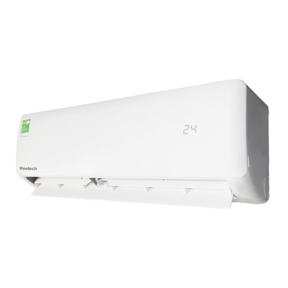
Summarization of Contents
Introduction
Safety Cautions
Essential safety precautions for repair work and operation, including warnings and cautions.
Icons Used
Explanation of icons used in the manual to attract attention to specific information.
Revision History
Details on the revisions made to the manual, including version and date.
Part 1 General Information
Applicable Models
Lists the indoor and outdoor unit models covered by this service manual.
Functions
Details the functions available for indoor and outdoor units, categorized by features.
Part 2 Specifications
Indoor Unit
Technical specifications for various indoor unit types: Wall Mounted, LSP Duct, and MSP Duct.
Outdoor Unit
Technical specifications for outdoor units, including models MKS and MKB series.
Part 3 Printed Circuit Board Connector Wiring Diagram
Indoor Unit
Wiring diagrams for indoor units, detailing PCB connections for different series.
Wireless Remote Controller Receiver
Wiring diagram for the wireless remote controller receiver, specifically for FDMR Series.
Wired Remote Controller
Wiring diagram for the wired remote controller, specifically BRC1E63 for FDMR Series.
Outdoor Unit
Wiring diagrams for outdoor units, covering MKS, MKB, and MKS90TVMG series.
Adaptor
Wiring details for Wireless LAN Adaptor and Remote Control PC-board Set.
Part 4 Functions and Control
Wall Mounted and LSP Duct Type Functions
Detailed explanation of functions for Wall Mounted and LSP Duct type indoor units.
MSP Duct Type Functions
Detailed explanation of functions for MSP Duct type indoor units.
Thermistor Functions
Explanation of the role and function of various thermistors in the system.
Control Specification
Technical details on control specifications, including mode hierarchy and frequency control.
Part 5 Remote Controller
Applicable Remote Controller
Lists which remote controllers are applicable to different Daikin series.
ARC466A19
Detailed explanation and operation of the ARC466A19 remote controller.
ARC433B76
Detailed explanation and operation of the ARC433B76 remote controller.
BRC086A22
Overview of the BRC086A22 remote controller, including its buttons and display.
BRC1E63
Overview of the BRC1E63 wired remote controller, including its buttons and LCD.
Part 6 Service Diagnosis
General Problem Symptoms and Check Items
Table of common symptoms, check items, details, and reference pages for troubleshooting.
Troubleshooting with LED
Troubleshooting guide based on LED indicators for indoor and outdoor units.
Service Diagnosis
Diagnostic methods for wireless remote controllers (ARC466 and ARC433 series).
Code Indication on Remote Controller
Lists error codes and their descriptions for indoor and outdoor units on the remote controller.
Troubleshooting for Wall Mounted and LSP Duct Type Indoor Unit
Specific troubleshooting steps for PCB abnormality, freeze-up, fan motor, and thermistors.
Troubleshooting for MSP Duct Type Indoor Unit
Troubleshooting steps for PCB, drain system, fan motor, thermistors, and signal errors.
Troubleshooting for Outdoor Unit
Comprehensive troubleshooting for outdoor unit issues like refrigerant shortage, voltage, wiring, and PCB.
Check
Detailed checks for components like thermistors, fan motors, Hall IC, and power supply.
Part 7 Trial Operation and Field Settings
Piping Diagrams
Diagrams illustrating the piping connections for indoor and outdoor units.
Wiring Diagrams
Wiring diagrams for indoor and outdoor units, showing PCB and component connections.
Operation Limit
Graphical representation of operation limits based on outdoor and indoor temperatures.
Part 8 Appendix
Piping Diagrams
Visual representations of refrigerant piping for various indoor and outdoor units.
Wiring Diagrams
Detailed wiring schematics for indoor and outdoor unit PCBs and components.
Operation Limit
Charts defining the operational boundaries for temperature and other parameters.


Need help?
Do you have a question about the CTKS71TVMG and is the answer not in the manual?
Questions and answers