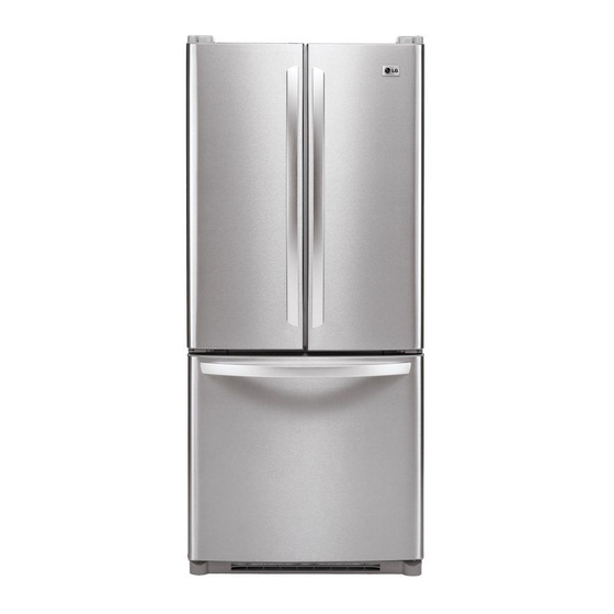
Summarization of Contents
SPECIFICATIONS
DIMENSIONS
Detailed dimensions of the refrigerator with diagrams.
DISASSEMBLY
3-1 DOOR
Procedure for removing and replacing the refrigerator door and its gasket.
3-2 DOOR ALIGNMENT
Steps to align refrigerator doors if the space between them is uneven.
3-3 FAN AND FAN MOTOR
Procedure for removing the fan and fan motor assembly.
3-4 DEFROST CONTROL ASSEMBLY
Details on the defrost sensor and fuse, and how to replace the control assembly.
3-5 LAMP
Instructions for replacing refrigerator and freezer compartment light bulbs.
3-6 CONTROL BOX-REFRIGERATOR
How to remove the refrigerator control box.
3-7 MULTI DUCT
Steps for removing the multi duct assembly.
ADJUSTMENT
4-1 COMPRESSOR
Explains the role and composition of the compressor and safety notes.
4-2 PTC-STARTER
Details on the PTC starter's composition, role, and usage.
4-3 OLP (OVERLOAD PROTECTOR)
Definition and role of the Overload Protector.
4-4 TO REMOVE THE COVER PTC
Procedure for removing the cover of the PTC.
TROUBLESHOOTING
6-1 COMPRESSOR AND ELECTRIC COMPONENTS
Troubleshooting flowchart for compressor and electrical component issues.
6-2 PTC AND OLP
Troubleshooting steps for PTC and OLP components.
6-3 OTHER ELECTRICAL COMPONENTS
Troubleshooting for other electrical components like fans and wiring.
6-4 SERVICE DIAGNOSIS CHART
Chart listing complaints, points to check, and remedies.
6-5 REFRIGERATION CYCLE
Troubleshooting chart for refrigeration cycle issues.
6-5-1 SEALED SYSTEM DIAGNOSIS
Diagnostic flowchart for sealed system issues.
OPERATION PRINCIPLE AND REPAIR METHOD OF ICEMAKER
7-1 OPERATION PRINCIPLE
Overview of the icemaker's operational principle and modes.
7-2 ICE MAKER FUNCTIONS
Details on Ice Making Mode, Harvest Mode, and Fill/Park Position.
7-2-5 Function TEST
Procedure and diagnosis table for testing icemaker functions.
7-3 DEFECT DIAGNOSIS FUNCTION
Error codes for ice maker water supply control panel.
DESCRIPTION OF FUNCTION & CIRCUIT OF MICOM
8-1 FUNCTION
General functions of the refrigerator controls and settings.
8-2 PCB FUNCTION
Overview of the Printed Circuit Board (PCB) functions and circuits.
8-3 RESISTANCE SEPECIFICATION OF SENSOR
Table of resistance specifications for various refrigerator sensors.
8-4 TROUBLESHOOTING
Troubleshooting guide for common refrigerator problems and solutions.
8-5 MAIN PWB ASSEMBLY AND PARTS LIST
Details of the Main Printed Circuit Board assembly and its parts.
8-6 PWB DIAGRAM
Schematic diagram of the Main Printed Circuit Board.
EXPLODED VIEW AND REPLACEMENT PARTS LIST
CASE PARTS
Exploded view and parts list for the exterior case components.
FREEZER PARTS
Exploded view and parts list for freezer compartment components.
REFRIGERATOR PARTS
Exploded view and parts list for refrigerator compartment components.
DOOR PARTS
Exploded view and parts list for refrigerator door components.
WATER and ICE MAKER PARTS
Exploded view and parts list for water and ice maker components.


Need help?
Do you have a question about the LFC20760ST and is the answer not in the manual?
Questions and answers