Table of Contents
Advertisement
Quick Links
SERVICE MANUAL
Ver. 1.1 2012.11
• The tuner and CD sections have no adjustments.
(BT3100P only)
FOR UNITED STATES CUSTOMERS. NOT
APPLICABLE IN CANADA, INCLUDING
IN THE PROVINCE OF QUEBEC.
POUR LES CONSOMMATEURS AUX
ÉTATS-UNIS. NON APPLICABLE AU
CANADA, Y COMPRIS LA PROVINCE DE
QUÉBEC.
(BT31PW/BT3100P only)
AUDIO POWER SPECIFICATIONS
CEA2006 Standard
Power Output: 17 Watts RMS 4 at
4 Ohms < 1% THD+N
SN Ratio: 80 dBA
(reference: 1 Watt into 4 Ohms)
Tuner section (BT31PW/BT3100P)
FM
Tuning range: 87.5 – 107.9 MHz
Antenna (aerial) terminal:
External antenna (aerial) connector
Intermediate frequency: 25 kHz
Usable sensitivity: 8 dBf
Selectivity: 75 dB at 400 kHz
Signal-to-noise ratio: 80 dB (stereo)
Separation: 50 dB at 1 kHz
Frequency response: 20 – 15,000 Hz
AM
Tuning range: 530 – 1,710 kHz
Antenna (aerial) terminal:
External antenna (aerial) connector
Intermediate frequency:
9,115 kHz or 9,125 kHz/5 kHz
Sensitivity: 26 μV
Tuner section (BT3100U)
FM
Tuning range: 87.5 – 108.0 MHz
Antenna (aerial) terminal:
External antenna (aerial) connector
Intermediate frequency: 25 kHz
Usable sensitivity: 8 dBf
Selectivity: 75 dB at 400 kHz
Signal-to-noise ratio: 80 dB (stereo)
Separation: 50 dB at 1 kHz
Frequency response: 20 – 15,000 Hz
MW/LW
Tuning range:
MW: 531 – 1,602 kHz
LW: 153 – 279 kHz
Antenna (aerial) terminal:
External antenna (aerial) connector
Intermediate frequency:
9,124.5 kHz or 9,115.5 kHz/4.5 kHz
Sensitivity: MW: 26 μV, LW: 45 μV
9-893-549-02
Sony Corporation
2012K33-1
©
2012.11
Published by Sony Techno Create Corporation
MEX-BT31PW/BT3100P/BT3100U/
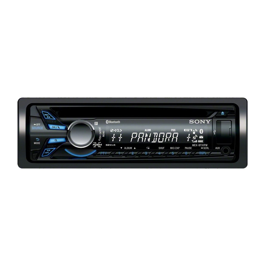
Photo: MEX-BT3100P
Model Name Using Similar Mechanism
Mechanism Type
Optical Pick-up Name
SPECIFICATIONS
Tuner section
MW
(BT3150U: E, Mexican,
Tuning range:
Argentina/BT3153U)
Antenna (aerial) terminal:
FM
Tuning range:
Intermediate frequency:
For non-Argentine models:
87.5 – 108.0 MHz (at 50 kHz step)
Sensitivity: 26 μV
87.5 – 108.0 MHz (at 100 kHz step)
SW
87.5 – 107.9 MHz (at 200 kHz step)
Tuning range:
For Argentine models:
87.5 – 107.9 MHz
FM tuning step (for non-Argentine models):
50 kHz/100 kHz/200 kHz switchable
Antenna (aerial) terminal:
Antenna (aerial) terminal:
External antenna (aerial) connector
Intermediate frequency:
Intermediate frequency: 25 kHz
Usable sensitivity: 8 dBf
Sensitivity:
Selectivity: 75 dB at 400 kHz
Signal-to-noise ratio: 80 dB (stereo)
CD Player section
Separation: 50 dB at 1 kHz
Signal-to-noise ratio: 120 dB
Frequency response: 20 – 15,000 Hz
Frequency response: 10 – 20,000 Hz
AM
Wow and flutter: Below measurable limit
Tuning range:
For non-Argentine models:
USB Player section
531 – 1,602 kHz (at 9 kHz step)
Interface: USB (Full-speed)
530 – 1,710 kHz (at 10 kHz step)
Maximum current: 1 A
For Argentine models:
Wireless Communication
530 – 1,710 kHz
AM tuning step (for non-Argentine models):
Communication System:
9 kHz/10 kHz switchable
Antenna (aerial) terminal:
Output:
External antenna (aerial) connector
Intermediate frequency:
For non-Argentine models:
Maximum communication range:
9,124.5 kHz or 9,115.5 kHz/4.5 kHz
(at 9 kHz step)
Frequency band:
9,115 kHz or 9,125 kHz/5 kHz
(at 10 kHz step)
Modulation method: FHSS
For Argentine models:
Compatible Bluetooth Profiles*
9,115 kHz or 9,125 kHz/5 kHz
Sensitivity: 26 μV
Tuner section
(BT3150U: Saudi Arabia model)
FM
Tuning range:
87.5 – 108.0 MHz
Antenna (aerial) terminal:
External antenna (aerial) connector
Intermediate frequency: 25 kHz
Usable sensitivity: 8 dBf
Selectivity: 75 dB at 400 kHz
Signal-to-noise ratio: 80 dB (stereo)
Separation: 50 dB at 1 kHz
Frequency response: 20 – 15,000 Hz
BT3150U/BT3153U
*1 The actual range will vary depending on
factors such as obstacles between devices,
531 – 1,602 kHz
magnetic fields around a microwave oven,
static electricity, reception sensitivity, antenna
External antenna (aerial) connector
(aerial)'s performance, operating system,
software application, etc.
9,124.5 kHz or 9,115.5 kHz/4.5 kHz
*2 Bluetooth standard profiles indicate the
purpose of Bluetooth communication
between devices.
Power amplifier section
SW1: 2,940 – 7,735 kHz
SW2: 9,500 – 18,135 kHz
Output: Speaker outputs
(except for 10,140 – 11,575 kHz)
Speaker impedance: 4 – 8 ohms
Maximum power output: 52 W 4 (at 4 ohms)
External antenna (aerial) connector
General
9,124.5 kHz or 9,115.5 kHz/4.5 kHz
Outputs:
Audio outputs terminal (front, rear/sub
switchable)
Power antenna (aerial)/Power amplifier control
terminal (REM OUT)
Inputs:
SiriusXM input terminal (BT3100P only)
Remote controller input terminal
Antenna (aerial) input terminal
MIC input terminal
AUX input jack (stereo mini jack)
USB port
Power requirements: 12 V DC car battery
(negative ground (earth))
Bluetooth Standard version 2.1 + EDR
Dimensions: Approx. 178 50 177 mm
(7
Mounting dimensions: Approx. 182 53 160 mm
Bluetooth Standard Power Class 2 (Max. +4
dBm)
(7
Mass: Approx. 1.2 kg (2 lb 11 oz)
1
Line of sight approx. 10 m (33 ft)*
Supplied accessories:
Remote commander: RM-X231
2.4 GHz band (2.4000 – 2.4835 GHz)
(BT31PW/BT3100P/BT3150U/BT3153U only)
Microphone (BT3100P only)
2
:
Parts for installation and connections (1 set)
A2DP (Advanced Audio Distribution Profile)
Design and specifications are subject to change
1.2
without notice.
AVRCP (Audio Video Remote Control Profile)
1.3
HFP (Handsfree Profile) 1.5
PBAP (Phone Book Access Profile)
SPP (Serial Port Profile)
US Model
MEX-BT31PW/BT3100P
Canadian Model
MEX-BT3100P
AEP Model
UK Model
MEX-BT3100U
E Model
MEX-BT3150U
Indian Model
MEX-BT3153U
MEX-BT4000P/BT4000U/
BT4050U/BT4054U
MG-101CA-188
DAX-25A
1
/
2 7 in) (w/h/d)
8
1
1
5
/
2
/
6
/
in) (w/h/d)
4
8
16
AUDIO SYSTEM
Advertisement
Chapters
Table of Contents

Related Manuals for Sony BT3100U


Summarization of Contents
SPECIFICATIONS
TUNER SECTION SPECIFICATIONS
FM/AM tuning ranges, IF, sensitivity, selectivity, S/N, separation, and frequency response details.
SERVICING NOTES
OPTICAL PICK-UP AND LASER DIODE HANDLING
Precautions for handling the optical pick-up block and checking laser diode emission safely.
DESTINATION SETTING AND CONFIRMATION
SETTING AND CONFIRMING DESTINATION CODE
Procedures to set and verify the unit's destination code via test mode entry.
SERVICE PRECAUTIONS AND PROCEDURES
COMPONENT REPLACEMENT AND INITIALIZATION
Notes on board replacement, Bluetooth initialization, connector cleaning, and demo mode cancellation.
BLUETOOTH FUNCTIONALITY TESTING
BLUETOOTH PHONE AND AUDIO CHECKS
Procedures to test hands-free phone and audio streaming functions via Bluetooth connection.
GENERAL INSTALLATION AND CONNECTION GUIDELINES
GENERAL PRECAUTIONS AND CONNECTION DIAGRAMS
Safety precautions, power supply notes, and detailed wiring connection diagrams.
MOUNTING AND INSTALLATION PROCEDURES
UNIT MOUNTING AND PANEL REMOVAL
Steps for mounting the unit, detaching the front panel, and fuse replacement.
DISASSEMBLY PROCEDURE
DISASSEMBLY FLOW AND MAJOR COMPONENT REMOVAL
Flowchart and instructions for removing major assemblies like fuse, CD deck, and boards.
TEST MODE OPERATIONS
TEST MODE SETTINGS AND MICROPHONE TEST
Procedures for entering test mode, loopback test, and external microphone detection display.
CIRCUIT DIAGRAMS - SERVO SECTION
SERVO SECTION BLOCK DIAGRAM
Block diagram illustrating the servo section's internal connections and components.
CIRCUIT DIAGRAMS - MAIN SECTION
MAIN SECTION BLOCK DIAGRAM
Block diagram showing the main section's functional units and interconnections.
CIRCUIT DIAGRAMS - PANEL/POWER SUPPLY SECTION
PANEL AND POWER SUPPLY BLOCK DIAGRAM
Block diagram detailing panel components, power supply, and regulators.
WIRING AND SCHEMATIC NOTES
CIRCUIT BOARDS LOCATION GUIDE
Identifies the physical location of various circuit boards within the unit.
SCHEMATIC DIAGRAM - MAIN BOARD (1/5)
MAIN BOARD SCHEMATIC (1/5) DETAILS
Schematic showing power supply, remote, and audio output connections.
PRINTED WIRING BOARD - MAIN SECTION (1/2)
MAIN BOARD COMPONENT SIDE LAYOUT (1/2)
Component placement diagram for the main board, component side.
PRINTED WIRING BOARD - KEY BOARD
KEY BOARD COMPONENT AND CONDUCTOR SIDE LAYOUT
Diagrams showing component placement on both sides of the key board.
SCHEMATIC DIAGRAM - KEY BOARD
KEY BOARD SCHEMATIC DETAILS
Schematic detailing the circuitry of the key board, including buttons and display.
COMPONENT FUNCTION DESCRIPTIONS
IC501 PIN FUNCTION DESCRIPTIONS
Detailed description of each pin's function for the Main System Controller IC501.
EXPLODED VIEWS
MAIN, FRONT PANEL, AND CD MECHANISM VIEWS
Exploded view diagrams of the main section, front panel, and CD mechanism deck with part numbers.
ELECTRICAL PARTS LIST
KEY BOARD COMPONENTS LIST
List of electrical parts for the key board, including LEDs, capacitors, connectors, and ICs.
COMPONENT AND ACCESSORY LISTS
ACCESSORIES LIST
List of supplied accessories like manuals and remote commanders, plus miscellaneous parts.
INSTALLATION PARTS LIST
PARTS FOR INSTALLATION AND CONNECTIONS
List of parts required for physical installation and electrical connections of the unit.
SUPPLEMENT-1: BOARD CHANGES
MAIN AND KEY BOARD DISCRIMINATION
Guide to differentiate between former and new versions of MAIN and KEY boards based on part numbers.
Need help?
Do you have a question about the BT3100U and is the answer not in the manual?
Questions and answers