Table of Contents
Advertisement
Advertisement
Chapters
Table of Contents

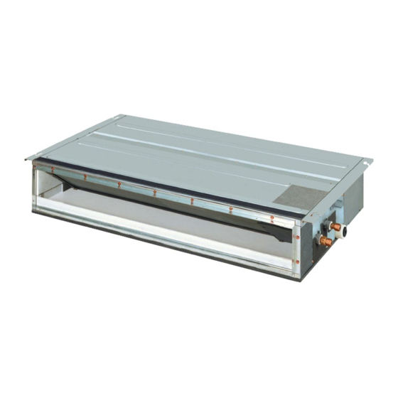
Related Manuals for Daikin VRV FXDQ40NDVE

Summarization of Contents
Specifications
2.1 FXDQ-PDVE(T) Specifications
Technical specifications for FXDQ-PDVE(T) units, including drain pump variants.
2.2 FXDQ-NDVE(T) Specifications
Technical specifications for FXDQ-NDVE(T) units, including drain pump variants.
Dimensions
3.1 FXDQ-PDVE(T) Model Dimensions
Detailed dimensional drawings for FXDQ-PDVE(T) units.
3.2 FXDQ-NDVE(T) Model Dimensions
Detailed dimensional drawings for FXDQ-NDVE(T) units.
Piping Diagrams
4. Piping Diagrams Overview
Visual representation of refrigerant piping connections for various models.
Wiring Diagrams
5. Indoor Unit Wiring Diagram
Diagram illustrating electrical connections within the indoor unit.
Electric Characteristics
FXDQ-PDVE(T) Series Electrical Data
Electrical parameters for PDVE models, including voltage, current, and power.
FXDQ-NDVE(T) Series Electrical Data
Electrical parameters for NDVE models, including voltage, current, and power.
Safety Devices Setting
FXDQ-PDVE(T) Models Safety Settings
Settings for protective devices like fuses and thermal protectors for PDVE.
FXDQ-NDVE(T) Models Safety Settings
Settings for protective devices like fuses and thermal protectors for NDVE.
Capacity Tables
8.1 Cooling Capacity for Te: Auto
Cooling capacity data for automatic temperature control.
8.2 Cooling Capacity for Te: 6°C
Cooling capacity data at 6°C.
8.3 Cooling Capacity for Te: 9°C
Cooling capacity data at 9°C.
8.4 Heating Capacity
Heating capacity values for various indoor conditions.
Fan Performances
9.1 FXDQ-PDVE(T) Series Fan Performance
Fan performance curves indicating airflow vs. static pressure for PDVE models.
9.2 FXDQ-NDVE(T) Series Fan Performance
Fan performance curves indicating airflow vs. static pressure for NDVE models.
Sound Levels
10.1 FXDQ-PDVE(T) Series Sound Levels
Sound pressure level data in dB for PDVE models across frequency bands.
10.2 FXDQ-NDVE(T) Series Sound Levels
Sound pressure level data in dB for NDVE models across frequency bands.
Centre of Gravity
11.1 FXDQ-PDVE(T) Models Centre of Gravity
Location of the center of gravity for PDVE units.
11.2 FXDQ-NDVE(T) Models Centre of Gravity
Location of the center of gravity for NDVE units.
Accessories
12.1 Optional Accessories (for Unit)
Optional items available for the indoor unit itself.
12.2 Optional Accessories (for Controls)
Optional accessories related to remote controllers and system controls.
Installation Manual
1. SAFETY PRECAUTIONS
Critical safety instructions and warnings for proper installation procedures.
2. BEFORE INSTALLATION
Pre-installation checks and preparations required for installation.
2-1 PRECAUTIONS
Specific environmental and handling precautions during installation.
2-2 ACCESSORIES
List of included installation accessories and their purpose.
2-3 OPTIONAL ACCESSORIES
Optional accessories for controls and unit installation.
Selecting Installation Site
3. SELECTING INSTALLATION SITE
Guidelines for choosing an appropriate location for unit installation.
4. PREPARATIONS BEFORE INSTALLATION
Preparatory steps and checks before mounting the unit.
Indoor Unit Installation
5. INDOOR UNIT INSTALLATION
Procedures for physically mounting and securing the indoor unit.
Refrigerant Piping Work
6. REFRIGERANT PIPING WORK
Instructions for safe and correct installation of refrigerant piping.
Drain Piping Work
7. DRAIN PIPING WORK
Procedures for installing the drain piping and ensuring proper drainage.
Installing the Duct
8. INSTALLING THE DUCT
Instructions for connecting the air duct system to the unit.
Electric Wiring Work
9-1 GENERAL INSTRUCTIONS
General guidelines and safety precautions for electrical wiring.
9-2 SPECIFICATIONS FOR FIELD SUPPLIED FUSES AND WIRE
Required specifications for fuses and wiring materials.
9-3 ELECTRICAL CHARACTERISTICS
Key electrical characteristics and ratings for the units.
Wiring Example
10-1 HOW TO CONNECT WIRINGS
Step-by-step guide for connecting electrical wiring to the unit.
No. 1 system When using 1 remote controller for 1 indoor unit
Wiring diagram for a single indoor unit with one remote controller.
No. 2 system For group control or use with 2 remote controllers
Wiring diagrams for group control and dual remote controller setups.
No. 3 system When including BS unit
Wiring diagram for a system including a BS unit.
10-2 CONTROL BY 2 REMOTE CONTROLLERS
Instructions for controlling one indoor unit with two remote controllers.
10-3 REMOTE CONTROL (FORCED OFF AND ON/OFF OPERATION)
How to use external signals for forced off and on/off operations.
10-4 CENTRALIZED CONTROL
Guidelines for setting up and configuring centralized control systems.
Field Setting and Test Run
11-1 SETTING THE STATIC PRESSURE SELECTION
Procedure for selecting the correct static pressure setting for the duct.
11-2 REMOTE CONTROL SETTING
How to configure settings using the remote controller.
11-3 SETTING THE FILTER SIGN DISPLAY INTERVAL
Configuring the filter maintenance reminder interval.
11-4 SETTINGS FOR SEPARATELY SOLD ACCESSORIES
Configuration steps for optional accessories.
11-5 SWITCHING TIME OF THE DRY OPERATION AT VRTsmart control SETTING
Adjusting dry operation timing for VRTsmart control.
Weight and Dimension
12. WEIGHT AND DIMENSION
Specifications for unit weight and overall dimensions.
Need help?
Do you have a question about the VRV FXDQ40NDVE and is the answer not in the manual?
Questions and answers