Table of Contents
Advertisement
Quick Links
READ AND SAVE THESE INSTRUCTIONS
WARNINGS
RISK OF ELECTRICAL SHOCK: Disconnect power to steam humidifier before opening
electrical access panel for humidistat installation.
RISK OF DAMAGE: Do not apply 120VAC to humidistat, humidistat is powered by 24VAC.
Disconnect power to humidistat prior to separating humidistat from its base.
EXCESS HUMIDITY: Do not set humidity higher than recommended. Condensation may
cause damage to structure and furnishings.
10011047 B2206528E 6.20
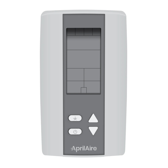
Model 63 and 5558
Automatic Digital Modulating
Control (ADMC)
Installation Instructions
WARNING
CAUTION
English 1
Advertisement
Table of Contents

Related Manuals for Aprilaire 5558


Summarization of Contents
Safety and Warnings
Risk of Electrical Shock
Disconnect power before opening electrical access panel for humidistat installation.
Risk of Damage
Do not apply 120VAC to humidistat; it is powered by 24VAC. Disconnect power before separating.
Excess Humidity Warning
Avoid setting humidity too high to prevent condensation damage to structure and furnishings.
Product Overview and Core Functions
Materials List
Lists components included in the Aprilaire ADMC package for Model 63 and Model 5558.
Principles of Operation
Explains how the ADMC provides precise humidity control via variable output based on set point and sensed humidity.
Key Component Features
Describes Duct Sensor, Temperature Compensation, and Blower Activation functionalities.
Installation and Wiring
Determine Location for Control
Mount ADMC on an interior wall, approx. 5' off floor, 18" from an outside wall, avoiding dead air spaces.
Determine Location for Duct Sensor
Install in return duct (space humidity) or supply duct (high limit), following specific clearance requirements.
Determine Location for Outdoor Temperature Sensor
Mount sensor out of direct sunlight, 3ft from exhaust vents, and above expected snow line.
Wiring Diagrams
Provides terminal descriptions and jumper settings for connecting the ADMC.
Setup and Operation Modes
Set Up
Initial configuration steps for the ADMC, including interface and symbols on display.
Program Mode
Detailed steps for programming ADMC functions like sensor calibration, set points, and control modes.
Operating Mode
Explains how to view and adjust humidity/temperature readings and set points in normal operation.
Technical Data
ADMC Technical Specifications
Details ADMC power supply, outputs, inputs, operating conditions, and dimensions.
Duct Sensor Technical Specifications
Details duct sensor power supply, output, operating temperature, storage, weight, and dimensions.
Need help?
Do you have a question about the 5558 and is the answer not in the manual?
Questions and answers