Advertisement
Quick Links
Advertisement

Related Manuals for CHINT NA1-2000X


Summarization of Contents
1. General
1.1 Application Scope
Describes the product's application and intended use in power distribution networks.
2. Operating Conditions
2.1-2.4 Operating Conditions
Details environmental requirements including temperature, altitude, air conditions, and pollution grade.
4. Main Technical Parameters
4.1 Technical Parameter Details
Lists detailed technical specifications such as rated current, voltage, and breaking capacity.
4.2 Capacity-Reducing Usage
Explains how breaker capacity is affected by ambient temperature.
5. Dimensions and Connection
NA8G-1600 Draw-out Type Dimensions
Provides physical dimensions and connection details for NA8G-1600 draw-out models.
NA8G-1600 Fixed Type Dimensions
Provides physical dimensions and connection details for NA8G-1600 fixed models.
NA8G-3200 Draw-out Type Dimensions
Provides physical dimensions and connection details for NA8G-3200 draw-out models.
NA8G-4000 Draw-out Type Dimensions
Provides physical dimensions and connection details for NA8G-4000 draw-out models.
NA8G-4000 Fixed Type Dimensions
Provides physical dimensions and connection details for NA8G-4000 fixed models.
NA8G-6300 Draw-out Type Dimensions
Provides physical dimensions and connection details for NA8G-6300 draw-out models.
6. Secondary Circuit Wiring
NA8G-1600 Secondary Circuit Diagram
Wiring diagram for the secondary circuit of the NA8G-1600 with standard controller.
Auxiliary Contact Modes
Explains the different configurations for auxiliary contacts available to customers.
7. Intelligent Controller and Protective Characteristics
7.1 User Interface of Standard Controller
Describes the buttons, indicators, and display of the standard intelligent controller.
7.2 Default Interface and Operation Method for Standard Controller
Explains how to navigate and operate the standard controller's default interface.
7.3 User Interface of Multifunctional Controller
Describes the buttons, indicators, and display of the multifunctional intelligent controller.
7.4 Default Interface and Menu Structure for Multifunctional Controller
7.4.1 Structure of Measurement Menu
Details the sub-menu structure for measuring electrical parameters.
7.4.2 Structure of Parameter Setup Menu
Details the sub-menu structure for setting various parameters.
7.4.3 Structure of Protection Parameter Setup Menu
Details the sub-menu structure for setting protection parameters.
7.4.4 Structure of History Record and Maintenance Menu
Details the sub-menu structure for accessing history records and maintenance logs.
7.6 Characteristic Parameters of Standard Type Intelligent Controller
7.6.1 Long Time-Delay Overcurrent Protection Characteristic
Presents characteristic curves and settings for long time-delay overcurrent protection.
7.6.2 Short-Circuit Short-Time-Delay Overcurrent Protection Characteristic
Presents characteristic curves and settings for short-circuit short-time-delay protection.
7.6.3 Short-Circuit Instantaneous Overcurrent Protection
Details characteristic curves and settings for short-circuit instantaneous overcurrent protection.
7.6.4 Single-Phase Earthing Fault Protection
Details characteristic curves and settings for single-phase earthing fault protection.
7.7 Explanation for Auxiliary Functions
7.7a Test Functions Explanation
Details how to use test functions for circuit breaker inspection and adjustment.
7.7b Fault Memory Explanation
Explains the fault memory feature and how it stores historical events.
8. Accessories
8.1 Under-Voltage Release
Describes the under-voltage release accessory and its operating characteristics.
8.2 Shunt Release
Describes the shunt release accessory and its operating characteristics.
8.3 Closing Electromagnet
Describes the closing electromagnet accessory and its operating characteristics.
9. Installation
9.1 Pre-Installation Checks
Lists essential items to check on the breaker panel before installation.
9.2 Installation Preparations and Manual Reading
Emphasizes reading the manual and preparing for installation.
9.3 Insulation Resistance Test
Details the procedure and requirements for the insulation resistance test.
9.4 Fixed Type Breaker Installation
Provides instructions for securely installing the fixed type circuit breaker.
9.5 Draw-out Type Breaker Installation
Provides instructions for installing the draw-out type circuit breaker into its bracket.
9.6 Wiring Copper Bar Specifications
Specifies requirements for primary circuit wiring copper bars according to IEC/EN 60947-2.
9.7 Grounding Requirement
States the necessity for substantial grounding of the circuit breaker.
Summary
5 Basic Frame Sizes
Highlights the availability of five basic frame sizes for the Air Circuit Breaker NA1.
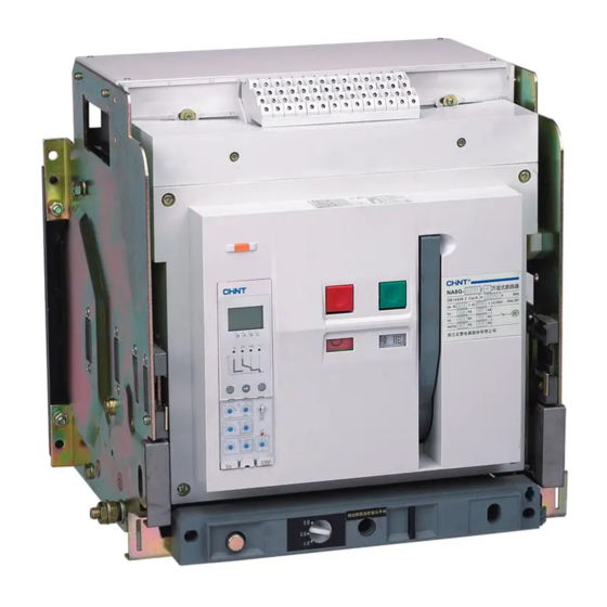
3. Structure
NA1 Series Structure and Components
Illustrates the assembly of the NA1 breaker, including drawer seat, body, and mounting plate.
4. Main Technical Parameter
NA1-1000X Technical Parameters
Lists detailed technical specifications for the NA1-1000X model.
NA1-2000X Series Technical Parameters
Lists detailed technical specifications for the NA1-2000X series models.
NA1-3200X Series Technical Parameters
Lists detailed technical specifications for the NA1-3200X series models.
NA1-6300X Series Technical Parameters
Lists detailed technical specifications for the NA1-6300X series models.
5. Dimensions and Connection
NA1-1000X Draw-out Type Dimensions
Provides physical dimensions and connection details for NA1-1000X draw-out models.
NA1-1000X Fixed Type Dimensions
Provides physical dimensions and connection details for NA1-1000X fixed models.
6. Secondary Circuit Wiring
NA1-1000X Secondary Circuit Wiring
Wiring diagram for the secondary circuit of the NA1-1000X model.
Standard Type (M/3M) Wiring
Describes wiring for standard type intelligent controllers.
Communication Type (H/3H) Wiring
Describes wiring for communication type intelligent controllers.
Six Pairs Change-over Contacts Wiring
Illustrates wiring for six pairs of change-over contacts.
NA1-2000X~6300X Standard Type Secondary Circuit Wiring
Wiring diagram for NA1 models with standard intelligent controller.
Auxiliary Contact Modes for Customer Use
Explains the different configurations for auxiliary contacts available to customers.
7. Installation
7.1 Installation Procedures
Provides step-by-step instructions for installing the circuit breaker.
7.1.5 Partitions and Busbars
Discusses the importance of partitions for air circulation and busbar connections.
7.1.7 Main Circuit Cable Connection
Describes how to connect main circuit cables to the breaker terminals.
7.1.8 Clamping and Tightening Torques
Specifies clamping procedures and torque values for connecting busbars.
13. Selectivity Protection
13.1 Selective Protection between NM8 and NA1
Compares selective protection settings between NM8 and NA1 circuit breakers.
13.2 Selective Protection in NA1
Details selective protection settings and tables for the NA1 series.
Intelligent Controller of NA1 Series
14 Protection Features of Intelligent Controller
Describes the protection capabilities and features of the intelligent controller.
14.1 M/H and 3M/3H Intelligent Controller UI
Explains the user interface, buttons, and display elements of M/H and 3M/3H controllers.
14.2 3M/3H Controller Default Interface and Menu Structure
Outlines the menu system and default interface of the 3M/3H intelligent controller.
14.3 Explanation of M/H Controller Symbols
14.3.1 Symbol Explanation
Provides a detailed explanation of the symbols used in the M/H controller interface.
14.3.2 Operation and Display Instruction
Guides on operating the controller and interpreting its display states.
14.4 Specifications of Characteristics
14.4.1 Over-Current Protection Characteristic Curve
Presents characteristic curves for various over-current protection settings.
14.4.2 Overload Long Time-Delay Protection
Details parameters and operating characteristics for overload long time-delay protection.
14.3 Short-Circuit Short-Delay Protection
Details parameters and operating characteristics for short-circuit short-delay protection.
14.4.4 Short-Circuit Instantaneous Protection
Details parameters and operating characteristics for short-circuit instantaneous protection.
14.4.5 Earthing Protection
Details parameters and characteristic curves for earthing protection.
15. Accessories
15.1 Under-Voltage Release
Describes the under-voltage release accessory, its types, and characteristics.
15.2 Shunt Release
Describes the shunt release accessory and its operating characteristics.
15.3 Closing Electromagnet
Describes the closing electromagnet accessory and its operating characteristics.
15.4 Motor-Driven Energy-Storage Mechanism
Describes the motor-driven energy storage mechanism and its availability.
15.5 Auxiliary Contact NO
Describes the normally open and normally closed auxiliary contact options.
15.6 Doorcase
Describes the doorcase accessory for sealing and protection.
15.7 Phases Barrier (Optional)
Describes the optional phases barrier accessory for insulation improvement.
15.8 Transparent Shield (Optional)
Describes the optional transparent shield accessory for enhanced protection.
15.9 Off Position Locking Mechanism
Explains the mechanism for locking the breaker in the OFF position.
15.10 Key Lock
Describes the key lock system for securing the breaker in the OFF position.
15.11 Cable Mechanical Interlock
Explains the cable mechanical interlock for breaker synchronization.
15.12 Connecting-rod Type Mechanical Interlock
Describes the connecting-rod type mechanical interlock for breaker synchronization.
16. Maintenance and Overhaul of Circuit Breaker
Safety Precautions
Lists critical safety measures to be followed before maintenance or overhaul.
Maintenance and Overhaul Cycle
Outlines the recommended maintenance and overhaul schedule based on environment.
16.1 Maintenance of Circuit Breaker
Details routine maintenance tasks for the circuit breaker.
16.1.1 Foreign Object Removal & 16.1.2 Dust Cleaning
Instructions for clearing foreign objects and cleaning dust from the breaker.
16.1.3 Bolt and Washer Inspection
Guidance on checking main circuit connecting bolts and earthing bolts.
16.1.4 Indication Check
Verifying the correctness and reliability of opening and closing indications.
16.2 Overhaul of Circuit Breaker
16.2.1 Connecting and Mounting Inspection
Details inspection procedures for connections and mounting during overhaul.
16.2.2 Insulating Property Test
Describes the insulation resistance test procedure after overhaul.
16.2.3 Operating Characteristic Inspection
Outlines inspection steps for operating characteristics after overhaul.
16.2.4 Inspection of Circuit Breaker Components
16.2.4.1 Face Shield Dismantling
Procedure for dismantling the face shield of the circuit breaker.
16.2.4.2 Operating Mechanism Inspection
Inspection of the operating mechanism for damage and lubrication.
16.2.4.3 Intelligent Controller Parameter Setting
Guidance on setting parameters for the intelligent controller.
16.3 Replacement of Accessories
16.3.1 Replacement of Fixed Accessories
Instructions for replacing fixed accessories like the panel and conductors.
16.3.2 Replacement of Draw-out Accessories
Instructions for replacing draw-out accessories like the body and conductors.
17. Common Failure Causes and Solutions
17.1 Troubleshooting Logic
Provides a flowchart for diagnosing common circuit breaker failures.
NA1-1000X~6300X Ordering Specification
1. NA1-2000X~6300X Fundamental Configurations
Lists standard configurations for NA1-2000X to 6300X models.
2. NA1-1000X Fundamental Configurations
Lists standard configurations for the NA1-1000X model.
3. NA1-2000X~6300X Operational Configuration (Additional Costs)
Lists optional configurations available for NA1-2000X to 6300X models.
4. NA1-1000X Operational Configuration (Additional Costs)
Lists optional configurations available for the NA1-1000X model.
Need help?
Do you have a question about the NA1-2000X and is the answer not in the manual?
Questions and answers