
Related Manuals for Broco PC/A-5V2HR


Summarization of Contents
Chapter 1 General Information and Safety Precautions
1-1. THERMAL CUTTING
Thermal torch cutting uses high temperatures to melt, burn through, or vaporize metal objects and mechanisms.
1-2. PRIME-CUT RESCUE AND RECOVERY TORCH KIT
Broco is a leading manufacturer of self-contained lightweight exothermic systems for emergency rescue and salvage.
1-3. WARNINGS
To avoid serious injury or death, all personnel shall heed these warnings.
1-4. SAFETY PRECAUTIONS
Failure to heed these safety precautions may result in death, severe bodily injury, or severe property damage.
Chapter 1 Equipment Description
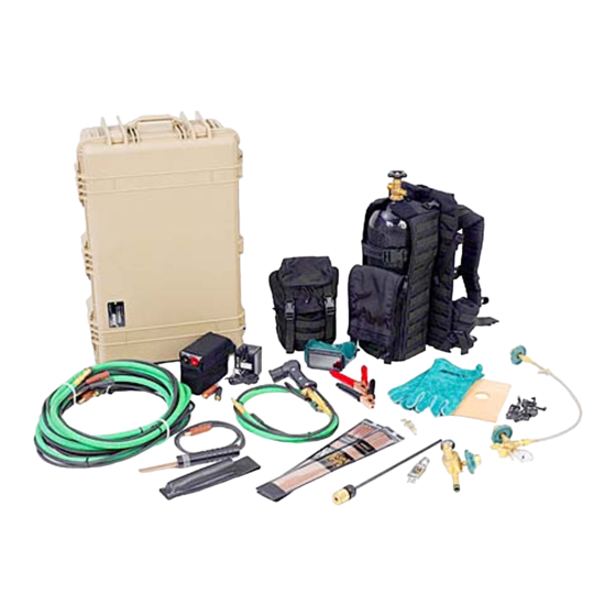
1-5. PC/A-5V2HR RESCUE & RECOVERY CUTTING TORCH SYSTEM
A combination of light weight and great cutting capability make this back-packed torch system ideal for confined space and remote operations.
Torch Assembly
The torch assembly consists of several parts. The torch body is a combination of handle, oxygen plug valve, and rod holder.
Cutting Rod
The kit is designed to use either 1/4" or 3/8" cutting rods. Standard rod length is 18 inches.
Leather Shield
The flexible leather shield acts as a hand guard and a splatter shield. It attaches to the torch over the collet nut.
Chapter 1 Equipment Description (cont.)
Oxygen Supply System
The oxygen (02) supply system consists of the following component parts.
Oxygen Regulator
The oxygen regulator has a hand-tighten cylinder connection (CGA 540) and a quick connect coupler outlet fitting.
Oxygen Cylinder
The all metal aluminum oxygen cylinder is a seamless aluminum compressed gas cylinder with a 45 cubic foot capacity.
Oxygen Hose & Cable Extension Set
The PC/A-5V2HR contains a 25 foot long hose and cable extension set (PC/EX-25).
Chapter 1 Equipment Description (cont.)
Battery Ignition Components
The battery ignition components are used to ignite the cutting rod by means of an electric arc.
Lightweight Battery
The lightweight battery (PC/BISLW) contains a rechargeable 12-volt, sealed, lead acid (gel-type) battery.
Striker Plate Assembly
The striker plate assembly (PC/SP-5), shown with leather sheath (PC/LSH), consists of a replaceable insulated copper grounding plate.
Battery Clamps
The battery clamps (PC/BAK) attach to the end of the striker plate cable and torch power cable by means of quick-connect fittings.
Chapter 1 Equipment Description (cont.)
Backpack Assembly
The back harness assembly features a comfortable backpack Molle platform with cylinder support enclosures, battery bag, rod extender and cutting rod holders.
Extender
The cutting rod extender (PC/TACXT16) included in the torch set extends the reach of the rod 16 inches.
Safety Equipment
The safety equipment included with each kit consists of welder's gloves and one pair of safety goggles with number 5 shade lense.
Chapter 1 Accessories
Transfill Hose Assembly
The Transfill hose assembly with bleed valve (PC/TFHBL) is used to transfer oxygen from a larger cylinder to the oxygen cylinder included in the torch kit.
Medical Oxygen Adapter
The medical oxygen adapter (M87-1) is used with oxygen cylinders having post type medical valves to provide a CGA 540 industrial oxygen outlet thread.
Component Case
The plastic Pelican™™ case (PC/C-1650) is foam lined with internal nylon straps to secure the hardware and absorb shock.
Rod Igniter
The RapidFire™™ cutting rod ignition cartridges are an alternative means of lighting the torch, eliminating the weight and bulk of the battery, striker plate and related cables.
Chapter 2 Preparation
2-1. PREPARING THE WORK AREA
Never operate the torch in explosive or flammable environments. Never cut into unknown material.
2-2. PRE-ASSEMBLY INSPECTION
Never use any equipment which is unsafe or appears to be unsafe. Always replace damaged or worn components.
Chapter 2 Assembly Procedures
2-3. OXYGEN SYSTEM
To reduce the risk of injury in the event of regulator failure, never stand directly in front of or directly behind the oxygen regulator.
General Oxygen System Information
The oxygen cylinders included with the Prime-Cut cutting torch kits are manufactured in compliance with all applicable US Department of Transportation requirements.
Export Kits and Adapters
For countries where US standard fittings are not accepted, Broco offers export versions and adapters for British standard components.
Chapter 2 Assembly Procedures (cont.)
BR-540 Adapter Usage
BR-540 adapter allows US standard regulators to be used with British standard oxygen cylinders.
BR-541 Adapter Usage
BR-541 adapter enables filling of oxygen cylinders using British standard connections.
Inspect and Wipe Clean Oxygen System
Inspect and wipe clean with a clean dry cloth all fittings, hoses, and cables. Ensure there is no grease, oil, or other contaminant.
Place Oxygen Cylinder in Backpack
Ensuring that the oxygen is turned off, place the oxygen cylinder into the backpack assembly.
Chapter 2 Assembly Procedures (cont.)
Connect Oxygen Regulator to Cylinder
Connect the oxygen regulator to the oxygen cylinder ensuring the regulator quick connect fitting for the oxygen hose is pointed straight down.
Connect Oxygen Hose and Attach Torch
Connect the five foot oxygen hose to the oxygen regulator and attach the torch assembly to the oxygen hose.
Open Oxygen Cylinder Valve Safely
Standing on the opposite side of the oxygen cylinder from the oxygen regulator, slowly open the oxygen cylinder valve to start the flow of oxygen.
Chapter 2 Ignition System
2-4. IGNITION SYSTEM OVERVIEW
The battery ignition components are used to ignite the cutting rod by means of an electric arc.
2-4-1. Lightweight Battery
The Lightweight Battery (PC/BISLW) contains a rechargeable 12-volt, sealed, lead acid (gel-type) battery.
Attach and Connect Lightweight Battery
Attach the Lightweight Battery to the Back Harness Assembly waist strap and connect the torch power cable to the torch.
Chapter 2 Ignition System (cont.)
Connect Power Cables to Battery and Receptacles
Connect the power cable to the battery and the striker plate cable to the battery by firmly seating the plugs into the receptacles.
2-4-2. Battery Adapter Clamps
The battery adapter clamps are employed when using any 12- or 24-volt (DC) power source other than the Lightweight Battery.
Chapter 2 Ignition System (cont.)
Connect 15 ft Power Cable to Torch (Battery Clamps)
Connect the 15 foot power cable to the torch by firmly seating the black plug in the hole in the back of the torch assembly.
Connect Power Cable to Battery Clamp (Battery Clamps)
Connect the other end of the 15 foot power cable to the black battery adapter clamp. Firmly seat the black plug into the receptacle.
Connect Striker Cable to Battery Clamp (Battery Clamps)
Connect the 15 foot striker plate cable to the red battery clamp by firmly seating the red plug into the receptacle.
Chapter 2 Accessory Equipment
2-5. LEATHER SHIELD INSTALLATION
The leather shield is intended to reduce sparks and spatter. Always use the leather shield when piercing.
2-6. ROD EXTENDER INSTALLATION
The rod extender is used to enable the operator to reach otherwise inaccessible places; make better use of existing cover; or create a stand-off.
Check for Leaks at Collet Nut (Rod Extender)
Check for oxygen leaks at the collet nut. If a leak exists, make sure rod extender is firmly seated.
Chapter 2 Accessory Equipment (cont.)
Inspect Collet Washer (Rod Extender)
Inspect the collet washer for damage and replace if necessary.
Insert Cutting Rod into Rod Extender
Insert the cutting rod into the rod extender as follows.
2-7. RAPIDFIRET™ CUTTING ROD IGNITERS
RapidFire™™ cutting rod ignition cartridges are used to light the cutting rods without the need for a battery, striker plate, and related cables.
General (Rod Igniters)
The rod igniter, utilized with the BROCO torch kits, contains an oxygen reactive material that is enclosed in a small, airtight, hermetically sealed glass vial.
Chapter 2 Igniter Information
Packaging, Transportation, and Storage (Igniters)
Igniters are sold in units of ten, packaged in airtight pouches, and should be stored in metal pails.
Disposal and Shelf Life (Igniters)
Reactive material should be exposed to air before disposal. Shelf life is estimated at three years inside the sealed foil pouch.
Chapter 3 Operating Instructions
3-1. TORCH OPERATION
The torch operates on the following principle. A regulated oxygen flow is fed through a consumable cutting rod.
Operating Procedures Introduction
Never operate the Prime-Cut torch without proper eye protection. Either a helmet with #5 face shield or #5 safety glasses shall be worn.
Chapter 3 Operating Instructions (cont.)
3-2. ROD INSERTION
Check to see that the collet in the torch assembly is the appropriate size to properly fit the rod being used.
Collet Size Selection (Rod Insertion)
3/16" collet with red washer; 1/4" and 3/8" with black washer; 1/2" with white or black washer.
Insert Cutting Rod into Collet
Insert the end of the cutting rod that has the recessed internal wires into the collet until it is firmly seated against the collet washer.
Chapter 3 Operating Instructions (cont.)
Tighten Collet Nut and Check for Leaks (Rod Insertion)
While maintaining slight pressure, tighten the collet nut to lock the rod in place. Check for oxygen leaks at the collet nut.
Remedies for Collet Nut Leaks
If none of the preceding remedy the leak, remove the torch from service and contact Broco customer service.
Chapter 3 Ignition Procedures
3-3-1. Ignition using the striker plate
Always hold the striker plate by the plastic handle to avoid electric shock. Never touch the copper plate.
Prepare for Striker Plate Ignition
Close plug valve, depress oxygen lever, open plug valve for light oxygen flow, point rod away from body.
Execute Striker Plate Ignition
Bring striker plate to rod, pull rod across plate at 45-90 deg angle. Maintain light pressure on lever.
Chapter 3 Ignition Procedures (cont.)
3-3-2. Ignition using RapidFire™™ igniter - Land Environment
Do not attempt to break the cutting rod igniter internal seal while the cutting rod is in the torch. Damage to collet washer may result.
Prepare Igniter for Land Use
Remove safety clip, place igniter on rod, break internal seal by tapping against surface, insert rod into torch.
Chapter 3 Ignition Procedures (cont.)
Execute Underwater RapidFire™™ Ignition
Hold rod tip in molten puddle, then raise rod and commence cutting.
3-3-3. Ignition using RapidFire™™ igniter - Underwater
The Broco Prime-Cut PC/A-5V2HR torch can be used for underwater cutting at depths to 30 fsw.
Prepare for Underwater Ignition
Close valve, depress lever, open valve for moderate oxygen flow, remove safety clip, place igniter on rod, break seal against surface.
Chapter 3 Operating Techniques
3-4-1. Piercing Operation
A pierce is accomplished by holding the torch with the rod at a 90 degree angle (perpendicular) to the pierce point.
Prepare for Piercing
Press burning tip into target material at 90 deg angle, insert rod tip into depression, increase oxygen flow for penetration.
Chapter 3 Operating Techniques (cont.)
Enlarge Hole and Remove Rod (Piercing)
Move rod in/out to enlarge hole, wash away material, remove rod from hole, extinguish torch.
3-4-2. Cutting Operation
Normal cutting is done by using a drag or pull technique. Push cutting may be performed on thinner materials.
Prepare for Cutting
Place burning tip against target at 45-90 deg angle, increase oxygen flow, keep rod in cut.
Chapter 3 Operating Techniques (cont.)
3-4-3. Gouging/Push Cutting Operation
Gouging is conducted by holding the rod at a very slight angle to the target material and pushing into the direction of the desired gouge.
Prepare for Gouging
Lay rod flat on work piece, increase oxygen flow, keep rod at slight angle, push rod in direction of gouge.
Complete Gouging and Extinguish
Lift rod tip from target material when gouge is complete, release lever to extinguish torch.
Chapter 3 Procedures
3-5. RESTART PROCEDURES
If cutting rod goes out, move torch away, check flow/pressure, re-ignite. Clear sealed rods by touching tip to striker plate or using new igniter.
3-6. SHUTDOWN PROCEDURES
Release lever to stop burning, loosen collet nut, remove rod, close cylinder valve, disconnect hoses and cables.
Disconnect Oxygen Hose and Regulator (Shutdown)
Disconnect oxygen hose from regulator. Remove regulator and pressure gauge/hose from cylinder.
Chapter 3 Procedures (cont.)
Inspect Cables, Hoses, and Store Kit (Maintenance)
Inspect cables/hoses for damage. Store kit in clean, dry place.
3-7. BATTERY CHARGING INSTRUCTIONS
CHARGE A NEW BATTERY BEFORE USING. CHARGE IMMEDIATELY AFTER EACH SUBSEQUENT USE.
3-7-1. Charging the Lightweight Battery
THE BROCO BATTERY MODEL PC/BISLW MAY TAKE UP TO 16 HOURS TO FULLY CHARGE.
Chapter 3 Procedures (cont.)
Connect Charger to Lightweight Battery
Plug charger connectors into battery receptacles. Plug charger into wall receptacle. Monitor indicator light.
3-7-2. Charging the 12-Volt/24-Volt Vehicle Battery
Always disconnect torch and striker plate power cables prior to charging the battery. Follow manufacturer's instructions.
3-8. TRANSFILLING OXYGEN CYLINDERS
Only personnel with proper training should attempt to fill a high pressure oxygen cylinder. Never let sparks or molten material contact the cylinder.
Chapter 3 Procedures (cont.)
b. Transfill procedures
Ensure transfill hose, adapters, cylinder valves, tools are clean and free from oil, grease, or contaminants.
Prepare for Transfill Operation
Position cylinders, purge valves, check seats, connect hose to source cylinder, purge hose assembly.
Chapter 3 Procedures (cont.)
Complete Transfill Process
Slowly open target and source cylinder valves, allow transference, repeat steps, close valves, open bleed valve, remove hose.
3-9. OXYGEN REGULATOR ADJUSTMENT PROCEDURE
Only personnel with proper training should attempt to adjust the oxygen regulator. Set regulator output pressure using oxygen only.
Chapter 3 Procedures (cont.)
b. Regulator adjustment procedures
Regulator output pressure adjustment requires the use of the optional accessory Regulator Adjusting Kit.
Adjust Regulator Output Pressure
While depressing the oxygen lever, adjust regulator output pressure using the adjusting screw on submersible or industrial type regulators.
Chapter 4 Scheduled Maintenance
4-1. PREVENTIVE MAINTENANCE
Preventive maintenance is the responsibility of the equipment operator. Conduct inspections, servicing, and cleaning.
Post-Use Cleaning and Inspection
Wipe down components, inspect collet assembly, inspect cables/hoses, clean torch after underwater use, rinse rods/igniters after salt water use.
Chapter 4 Scheduled Maintenance (cont.)
Striker Plate Maintenance
Remove slag build-up, wipe cable assembly, recharge battery as needed.
Oxygen Cylinder Maintenance
Inspect/clean cylinder, check pressure, perform annual visual inspection, and hydrostatic testing every 3 or 5 years.
Chapter 4 Scheduled Maintenance (cont.)
4-2. PREVENTIVE MAINTENANCE PROCEDURES
Perform quarterly PMCS checks. Inspect Oxygen Cylinder, Regulator, and Hose Assemblies.
Regulator and Hose Assembly Checks
Check Regulator body/fittings, nipple/O-ring, valve nut, female quick disconnect, and high pressure gauge.
Torch Assembly Checks
Inspect Torch Body and Collet Nut for dents or damage. Check serviceability of threading.
Chapter 4 Scheduled Maintenance (cont.)
Torch Assembly Component Checks
Inspect Collet, Collet Washer, Flash Arrestor, Screen, Valve Assembly, Plug Valve, and Quick Connects.
Striker Plate Assembly Checks
Inspect Striker Plate Handle, Copper Plate, Wooden Insulator, Wire Lug, Cable, and CAMLOK connectors.
Lightweight Battery and Harness Checks
Inspect Battery Charger and Back Harness Assembly for damage, wear, and proper function. Check battery charge.
Chapter 4 Scheduled Maintenance (cont.)
Backpack and Case Checks
Inspect Backpack Harness, Tank Strap, Case, and Rod Quivers for proper function and damage.
Accessory Checks
Check Rod Extender, Leather Striker Holder, Leather Shield, Leather Gloves, and Safety Glasses for wear and damage.
Chapter 5 Troubleshooting
Section I. OXYGEN SYSTEM MALFUNCTIONS
This guide assists in determining the probable causes of torch malfunctions and their associated repairs.
5-1. OXYGEN LEAKS
Troubleshooting Oxygen Leaks: Collet Nut, Control Valve Nut, and Valve Shut-off issues.
Oxygen Leaks at Collet Nut or Control Valve Nut
Addresses leaks at collet nut (rod seating, washer issues) and control valve nut (loose nut, damaged O-ring).
Chapter 5 Troubleshooting (cont.)
Oxygen Valve Does Not Shut Off
Addresses damaged threads, dirty/worn rubber gasket, or worn valve stem O-ring.
5-2. UNEVEN OXYGEN FLOW
Troubleshooting Uneven Oxygen Flow: Flash arrestor, screen, or torch cleanliness issues.
Troubleshooting Uneven Oxygen Flow
Addresses issues with dirty/worn flash arrestor or screen, or a dirty torch.
Chapter 5 Troubleshooting (cont.)
Section II. VALVE STEM MALFUNCTIONS
Troubleshooting Valve Stem Malfunctions: Sticking Control Valve.
5-3. STICKING CONTROL VALVE
The valve stem will not move freely while depressing and releasing the oxygen control lever.
Section III. CUTTING ROD MALFUNCTIONS
Troubleshooting Collet / Cutting Rod Malfunctions: Collet Problems.
5-4. COLLET PROBLEMS
The cutting rod will not fit into the collet in the torch.
Chapter 6 Corrective Maintenance
Section I. INTRODUCTION
This chapter contains inspection, disassembly, and reassembly procedures required for corrective maintenance on the Broco Prime-Cut Tactical torch kits.
Section II. ADJUSTMENTS, ALIGNMENTS, AND REPAIRS
Adjustments, Alignments, and Repairs for Broco Prime Cut torch systems.
6-2. FLASH ARRESTOR AND SCREEN
Do not operate the torch without a flash arrestor or screen. It performs an important safety function.
Chapter 6 Corrective Maintenance (cont.)
Remove, Clean, or Replace Flash Arrestor/Screen
Always remove, clean, and/or replace the flash arrestor and flash arrestor screen after the torch has been submerged in water.
Inspect Flash Arrestor and Screen
Inspect the flash arrestor and screen for damage, wear, corrosion, and/or clogging. Clean or replace as needed.
Reassemble Flash Arrestor Assembly
Place the flash arrestor screen inside the flash arrestor. Place the flash arrestor into the torch assembly.
Need help?
Do you have a question about the PC/A-5V2HR and is the answer not in the manual?
Questions and answers