Table of Contents
Advertisement
OWNER'S MANUAL
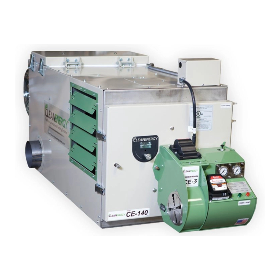
CE-140 Mul -Oil Furnace
CE-180 Mul -Oil Furnace
CE-250 Mul -Oil Furnace
With CE-3 Burner
CE-330 Mul -Oil Furnace
CE-440 Mul -Oil Furnace
With CE-4 Burner
PO Box 1341, 540 Maple Street, Honey Brook, PA 19344
www.CleanEnergyHeatingSystems.com
WARNING:
vapors and liquids in the vicinity of this or any appliance.
Heating Systems
Clean Energy Heating Systems, LLC
(888) 519-2347
For your safety - DO NOT store gasoline or other flammable
®
CE70155
Advertisement
Table of Contents

Related Manuals for Clean Energy CE-440


Summary of Contents for Clean Energy CE-440
- Page 1 ® Heating Systems OWNER’S MANUAL CE-140 Mul -Oil Furnace CE-180 Mul -Oil Furnace CE-250 Mul -Oil Furnace With CE-3 Burner CE-330 Mul -Oil Furnace CE-440 Mul -Oil Furnace With CE-4 Burner CE70155 Clean Energy Heating Systems, LLC PO Box 1341, 540 Maple Street, Honey Brook, PA 19344 www.CleanEnergyHeatingSystems.com...
- Page 2 Underwriters Laboratories File # MH48829 TRADEMARKS The Clean Energy logo is a registered trademark of Clean Energy Heating Systems, LLC. COPYRIGHT Copyright © 2019 Clean Energy Heating Systems, LLC. This manual may not be reproduced or distributed without the prior written permission of: Clean Energy Heating Systems, LLC.
-
Page 3: Table Of Contents
TABLE OF CONTENTS SAFETY CONSIDERATIONS AND GUIDELINES.............. 4 TIPS FOR MAINTAINING HIGH PERFORMANCE............6 FURNACE ASSEMBLY....................... 7 (1) Installing the blower................... 7 (2) Air discharge configuration................10 - Unit Heater (Free Air with no ductwork)............10 - Central Furnace (ductwork installed)............12 (3) Installing the combustion chamber target............ -
Page 4: Safety Considerations And Guidelines
SAFETY CONSIDERATIONS AND GUIDELINES HAZARD DEFINITIONS: NOTICE: Intended to clarify or bring special attention to previous information. CAUTION: Indicates a hazardous situation, which can result in minor or moderate personal injury if not avoided. WARNING: Indicates a hazardous situation, which can result in death or serious personal injury if not avoided. - Page 5 Chimney’s, Fireplaces, Vents and Solid Fuel Burning Appliances Likewise, the installation, operation, and maintenance of this equipment in Canada must be done by qualified personnel according to instructions in the Clean Energy Heating Systems Owner’s Manual and in accordance with all regulations and authorities having...
-
Page 6: Tips For Maintaining High Performance
SAFETY CONSIDERATIONS AND GUIDELINES GUIDELINES FOR USED OIL TANKS: WARNING: To avoid serious injury or death, only store petroleum based substances in the oil supply tank (the following are approved fuels): (1) Used Crankcase Oil (2) Used Automatic Transmission Fluid (ATF) (3) Used Hydraulic Oil (4) #2 Fuel Oil (Diesel Fuel) DO NOT put flammable or corrosive substances such as gasoline, chlorinated solvents,... -
Page 7: Furnace Assembly
Installing the Blower (CE-140, CE-180, and CE-250): (1) Refer to Figure 2. (2) Remove the three shipping brackets (CE 250 blower assembly only). - Page 8 (3) mounted over the motor shaft CE70197 Figure 2: Blower Assembly Installation (CE-140, CE-180, and CE-250) CAUTION: Three shipping brackets are installed on the CE 250 Blower Assembly and must be removed before operation. Installing the Blower (CE-330 and CE-440): (1) Refer to Figure 2A.
- Page 9 FURNACE ASSEMBLY (6) Install the blower pulley and motor pulley. Use a straight edge to make sure the pulleys are installed on the same plane. (7) Install the belt on the pulleys and tighten the tensioning bracket to maintain proper belt tension.
-
Page 10: Air Discharge Configuration
FURNACE ASSEMBLY Air Discharge Configurations: Your Clean Energy Heating System may be installed in one of two ways: Unit Heater - Louvers are installed over the air outlet opening(s) to direct the hot air flow in the desired direction. Central Furnace (Static Pressure) - Duct work applications with less than 0.30”... - Page 11 FURNACE ASSEMBLY CE70160 Figure 4: Installing the Louvers Splitting the Air Outlet Openings Between Both Sides CE70161 Figure 5: Installing the Louvers Splitting the Air Outlet Openings Between one Side and Bottom...
-
Page 12: Central Furnace (Ductwork Installed)
Only connect ductwork to the side air outlets on the furnace. DO NOT install ductwork on the bottom air outlet of the furnace. Refer to the tables below for air flow specifications. CE-140 Louvers Mounted on Furnace No Louvers Installed / Ductwork Installed on Furnace No Ductwork 0.30”... -
Page 13: Installing The Combustion Chamber Target
FURNACE ASSEMBLY Installing the Combustion Chamber Target: NOTICE: Damage to the combustion chamber may occur if the furnace is used with a damaged or missing target. Inspect the target regularly for proper positioning and wear. (1) Refer to Figure 6 to view the proper position of the combustion chamber target. (2) Open the front door of the furnace by loosening the two over-center latches and swinging the door open. -
Page 14: Installing The Connector Block And Oil Line
FURNACE ASSEMBLY WARNING: To prevent the risk of electrical shock, shut OFF main power to the furnace before connecting or disconnecting the burner power cord. (4) Refer to Figure 8 (5) Line up the key in the receptacle with the slot in the cord. -
Page 15: Furnace Installation
FURNACE INSTALLATION Refer to Figure 10 for a typical furnace installation illustration. Installation of your furnace will include the following steps: (1) Selecting a location (2) Mounting the furnace in position (3) Connecting the electrical supply to the furnace (4) Installing the chimney components (5) Positioning the oil storage tank (6) Installing the metering pump system and oil lines (7) Connecting the compressed air line... -
Page 16: Selecting A Location
FURNACE INSTALLATION WARNING: Carefully follow all installation instructions for safe and efficient operation. Select a location: There are several considerations when selecting a location for your new furnace: (1) Do not obstruct shop personnel or equipment (2) Find a location where the warm air will be evenly distributed. (3) The installation must meet the clearance to combustible material requirements (Figure 11) (4) The location must be safely accessible for maintenance and service (5) The installation must comply with all local codes and regulations... -
Page 17: Mounting The Furnace In Position
FURNACE INSTALLATION Mounting the furnace in position: WARNING: Codes may require that the furnace is mounted eight (8) feet above the floor if there is potential for gasoline fumes. Refer to NFPA 88B, Standard for Repair Garages. WARNING: Use adequate structural members to safely bear the weight of the furnace when either hanging it from the ceiling or mounting it on a stand. -
Page 18: Connecting The Electrical Supply
ONLY a qualified electrician should run wire and make connections to the furnace. All wires must be the proper gauge and run in approved electrical conduit. All wiring must meet the requirements of the National Electrical Code. Electrical Requirements: CE-140 CE-180 120 V / 60 Hz 120 V / 60 Hz... -
Page 19: Installing The Chimney Components
(2) Observe the following requirements when installing the chimney: • The CE-140, CE-180 and CE-250 furnace models require 6” I.D. stack components. • The CE-330 and CE-440 furnace models require 8” I.D. stack components. • Have a minimum of 10 feet vertical chimney to ensure -.02” w.c. draft over fire. - Page 20 FURNACE INSTALLATION "CLASS A" STACK CAP NON-RESTRICTIVE TYPE 10 FT. BAROMETRIC DAMPER SET DRAFT OVER FIRE AT -0.02 IN. W.C. CE70168 Figure 14: Typical Through-the-Roof Chimney Illustration "CLASS A" STACK CAP NON-RESTRICTIVE TYPE 10 FT. SET DRAFT OVER FIRE AT -0.02 IN.
-
Page 21: Oil Storage Tank Setup
FURNACE INSTALLATION Oil storage tank setup: PRESSURE OIL LINE TO THE HEATING EQUIPMENT VENT SUCTION OIL LINE PRESSURE DRAIN PAN RELIEF WITH SHUT OFF RETURN OIL LINE VALVE EMERGENCY VENT SUCTION OIL LINE IS ONE CONTINUOUS PIECE OF COPPER TUBING INSTALLED THROUGH THE SLIP FITTING CHECK VALVE CLEAN OUT... - Page 22 FURNACE INSTALLATION PRESSURE OIL LINE TO THE HEATING EQUIPMENT (3/8" OR 1/2" COPPER TUBING) MINI BALL VALVE FILL BALL VALVE BALL VALVE BLEEDER VALVE USED FOR VACCUUM TEST VACUUM GAUGE SUCTION OIL CANISTER FILTER LINE TO TANK (1/2" COPPER TUBING) PRESSURE RELIEF RETURN OIL LINE TO THE TANK (1/4"...
- Page 23 FURNACE INSTALLATION PRESSURE OIL LINE TO THE HEATING EQUIPMENT (3/8" OR 1/2" COPPER TUBING) MINI BALL VALVE FILL BALL VALVE BALL VALVE BLEEDER VALVE USED FOR VACCUUM TEST VACUUM GAUGE CANISTER FILTER SUCTION OIL LINE TO TANK (1/2" COPPER TUBING) PRESSURE RELIEF RETURN OIL LINE TO THE TANK (1/4"...
- Page 24 FURNACE INSTALLATION 1/2" MNPT SLIP-THROUGH 1/2" MNPT X 1/4" FITTING COMPRESSION 2" DUPLEX FITTING SUCTION OIL LINE (1/2" COPPER TUBING) PRESSURE RELIEF RETURN OIL LINE (1/4" COPPER TUBING) DETAIL A SUCTION OIL LINE IS ONE CONTINUOUS PIECE OF COPPER TUBING INSTALLED THROUGH THE SLIP FITTING 1/2"...
- Page 25 FURNACE INSTALLATION Installing the pressure oil line to the furnace: (1) Refer to Figure 21. (2) Determine the length of copper tubing needed for the pressure line (from pump to furnace) and use the appropriate sized tubing. If the pressure line is less than 100 feet, 3/8” copper tubing can be used.
-
Page 26: Connecting The Compressed Air Line
FURNACE INSTALLATION OIL INLET PORT (1/4" NPT) ALUMINUM CONNECTOR BLOCK CE70170 SWIVEL FITTING Figure 22: Connecting the Pressure Oil Line to the Connector Block Connecting the Compressed Air Line: (1) Refer to Figure 23. (2) mount a water trap / air regulator (adjusted CE70171 to 50 psi) and shut-off valve close to the furnace. -
Page 27: Installing The Wall Thermostat
FURNACE INSTALLATION Installing the wall thermostat: (1) Use the digital wall thermostat provided with the furnace. (2) Mount the wall thermostat according to the instructions provided with the thermostat. (2) Mount the thermostat on an interior wall and in a location that will be shielded from drastic temperature changes such as a door being opened. -
Page 28: Starting And Adjusting The Burner
STARTING AND ADJUSTING THE BURNER Preparing the burner for start up: (1) Plug the black cord into the top of the burner. (2) Turn on electrical power to the furnace. (3) Allow the burner heater element sufficient time to warm up the burner (time will vary according to ambient temperature). -
Page 29: Resetting The Oil Primary Control
(3) When the combustion chamber has cooled, and there is no vapor or excess oil in the combustion chamber, push the reset button for 3 seconds and release. (4) If the burner does not restart contact the Clean Energy Heating Systems service department. -
Page 30: Setting The Draft
RESETTING THE OIL PRIMARY CONTROL Resetting the burner from restricted lock out: NOTICE: If the control locks out three times before a call for heat is satisfied, it will enter PRIMARY CONTROL restricted lockout mode in order to limit the RESET BUTTON amount of unburned oil in the combustion chamber. -
Page 31: Maintenance
MAINTENANCE Periodic Maintenance Schedule: (1) Clean the oil filter and pump head screen........once a year (2) Clean sludge and water from the tank........once a year (3) Clean ash from the heat exchanger..........1200 hours (4) Flush the nozzle adapter heater block........2000 to 3000 hours Cleaning the oil canister filter screen: (1) Place a container under the canister filter to catch any released oil. - Page 32 MAINTENANCE Cleaning sludge and water from the bottom of the tank: NOTICE: Because of the nature of used oil handling practices, it is very difficult to keep all water and sludge out of the used oil supply. Drain the used oil supply tank at least once a year to ensure no unwanted substance is being delivered to the furnace.
- Page 33 MAINTENANCE CE70174 Figure 30: Cleaning Ash From the Heat Exchanger Flush the nozzle adapter heater block: (1) Refer to Figure 31. (2) Open the igniter hinge cover on the burner. (3) Remove the electrode (4) Loosen the oil line swivel fitting with a 9/16” open end wrench. (5) Disconnect the air line by pushing on the release ring and pulling the tube out of the fitting.
- Page 34 MAINTENANCE OIL LINE SWIVEL FITTING NOZZLE ADAPTER HEATER BLOCK RELEASE RING ON AIR LINE FITTING QUICK DISCONNECT ELECTRICAL CONNECTOR CE70175A Nozzle adapter heater block with all components and plugs removed. CE70162 Figure 31: Flushing the Nozzle Adapter Heater Block...
-
Page 36: Troubleshooting Guide
Clean Energy Hea ng Systems Troubleshoo ng Sequence BURNER DOES NOT ATTEMPT TO START GREEN LIGHT GREEN LIGHT IS ON IS OFF MAKE SURE CIRCUIT MAKE SURE BURNER PRIMARY PRIMARY RED LIGHT IS BREAKER / POWER CONNECTOR CORD CONTROL CONTROL... - Page 37 Clean Energy Hea ng Systems Troubleshoo ng Sequence THE BURNER IGNITES BUT WILL NOT STAY RUNNING THE OIL GAUGE IS THE OIL GAUGE IS BOUNCING OR STEADY AND NOT FLUTTERING BOUNCING THERE IS AIR IN THE OIL LINE. PRIME THE...
-
Page 38: Furnace Dimensions
FURNACE DIMENSIONS 76 7 8 CE 140 • 6” Chimney Pipe Diameter • Threaded Rod Knock Outs 27 1 2 44-5/8” X 21-3/8” 49 5 27 1 2 28 1 4 CE70176 82 3 4 CE 180 • 6” Chimney Pipe Diameter 27 1 2 •... - Page 39 FURNACE DIMENSIONS 99 1 4 CE 250 • 6” Chimney Pipe Diameter • Threaded Rod 27 1 2 Knock Outs 63-5/8” X 21-3/8” 68 1 2 27 1 2 28 1 4 CE70178 110 5 8 CE 330 • 8” Chimney Pipe Diameter •...
- Page 40 FURNACE DIMENSIONS 126 1 2 CE 440 • 8” Chimney Pipe Diameter • Threaded Rod Knock Outs 79-1/2” X 25-1/2” 84 1 2 CE70210...
-
Page 41: Wire Diagrams
WIRE DIAGRAMS CE-140 AND CE-180 FURNACE CABINET WIRE DIAGRAM: TO BLOWER CE-140 / CE-180 BLACK POWER WHITE USE COPPER 120 VAC CONDUCTORS ONLY 1 PH BLACK WHITE DPST POWER ORANGE SWITCH PUMP BURNER DRAFT CONNECTOR AUTO INDUCER HIGH CORD SWITCH... - Page 42 WIRE DIAGRAMS CE-250 FURNACE CABINET WIRE DIAGRAM: TO BLOWER CE-250 BLACK POWER WHITE 120 VAC USE COPPER CONDUCTORS ONLY 1 PH BLACK WHITE DPST POWER ORANGE SWITCH PUMP BURNER DRAFT CONNECTOR AUTO INDUCER HIGH CORD SWITCH HIGH (OPTIONAL) LIMIT LIMIT 75066 CE-250 BLOWER WIRE DIAGRAM: N.O.
- Page 43 WIRE DIAGRAMS CE-330 and CE-440 FURNACE CABINET WIRE DIAGRAM: TO BACK CE-330 USE COPPER ELECTRICAL BOX CONDUCTORS ONLY CE-440 BLACK WHITE DPST POWER SWITCH PUMP BURNER CONNECTOR DRAFT CORD AUTO HIGH INDUCER SWITCH HIGH (OPTIONAL) LIMIT LIMIT 75067 CE-330 and CE-440 BLOWER WIRE DIAGRAM: CE-330 / CE-440 TO BLOWER 230 Volts...
- Page 44 WIRE DIAGRAMS CE-3 BURNER WIRE DIAGRAM (USED ON CE-140, CE-180, AND CE-250):...
- Page 45 WIRE DIAGRAMS CE-4 BURNER WIRE DIAGRAM (USED ON CE-330 and CE-440):...
- Page 46 WIRE DIAGRAMS METERING PUMP GEARMOTOR WIRE DIAGRAM: PUMP MOTOR BLUE FURNACE 7.5 MFD SCHEMATIC 370 VAC BLACK CE70196...
-
Page 47: Burner Power Switch
BURNER POWER SWITCH Review the figure below along with the wire diagram for your furnace model for additional information about the Burner power Switch. Power to the burner must be shut off prior to disconnecting or connecting the Burner Connector Cord. CE70180 Burner Power Switch Burner Connector Cord... -
Page 48: Parts Diagrams
CE-3 / CE-4 BURNER ASSEMBLY... - Page 49 ITEM PART # DESCRIPTION QTY. 60301 CE 3 EZ Burner Assembly 60401 CE 4 EZ Burner Assembly 65030 Burner Housing Top Cover 65029 Ignitor Hinge Plate 30025 Burner Receptacle (5 Wire) 58045 Machine Screw 10 32 x 7/8 58040 Washer Neoprene Bonded #10 1/2 OD 30001 Electrode 65041...
- Page 50 NOZZLE ADAPTER / HEATER BLOCK ASSEMBLY...
- Page 51 ITEM PART # DESCRIPTION QTY. 60020 Nozzle Adapter Heater Block Assembly 50250 O ring Nozzle 40005 9 5 Nozzle 58054 Machine Screw 10 32 x 3/8 Z Ext Tooth LW 20008 Nozzle Adaptor Bracket Three Legs 50067 Plug Hex Socket 30011 Thermostat 150F Heater 50364...
- Page 52 MANIFOLD BLOCK ASSEMBLY...
- Page 53 ITEM PART # DESCRIPTION QTY. 30002 Heat Element 50054 Air Pressure Switch 58029 Machine Screw 8 32 x 3/8 Z 30010 Terminal Block Burner 50188 Plug Hex Socket 1/8 NPT w/ Dry Seal 50062 Tube Fitting 1/8T x 1/8 MNPT 50067 Plug Hex Socket 1/16 NPT w/ Dry Seal 50064...
- Page 54 CE-140 FURNACE CABINET...
- Page 55 ITEM PART # DESCRIPTION QTY. 10140 CE 140 (w/ Burner, Pump, and Blower) 60140 CE 140 Furnace Cabinet Only 20077 6" Shroud. Ring 90015 Duct Cap 6" 20045 Louvers 20144 Shrouding RH Side CE 140 20075 Front Door Hinge 50007 Oil Connector Block 50042 Swivel 3/8 Comp 1/4 NPT...
- Page 56 CE-180 FURNACE CABINET...
- Page 57 ITEM PART # DESCRIPTION QTY. 10180 CE 180 (w/ Burner, Pump, and Blower) 60180 CE 180 Furnace Cabinet Only 20077 6" Shroud. Ring 90015 Duct Cap 6" 20045 Louvers 20072 Shrouding RH Side CE 180 20075 Front Door Hinge 50007 Oil Connector Block 50042 Swivel 3/8 Comp 1/4 NPT...
- Page 58 CE-140 / 180 BLOWER...
- Page 59 ITEM PART # DESCRIPTION QTY. 60005 CE 140 / CE 180 Blower Assembly 50013 Blower CE180 65013 Blower Mtr Bracket (3/4 HP Motor) 30005 Motor 3/4 HP. 30012 Capacitor 15 MFD 370V 30018 Boot Capacitor 50018 Blower Guard...
- Page 60 CE-250 FURNACE CABINET...
- Page 61 ITEM PART # DESCRIPTION QTY. 10250 CE 250 (w/ Burner, Pump, and Blower) 60250 CE 250 Furnace Cabinet Only 20077 6" Shroud. Ring 90015 Duct Cap 6" 20090 Shrouding RH Side CE 250 20045 Louvers 20075 Front Door Hinge 50007 Oil Connector Block 50042 Swivel 3/8 Comp 1/4 NPT...
- Page 62 CE-250 BLOWER...
- Page 63 ITEM PART # DESCRIPTION QTY. 60006 CE 250 Blower Assembly 50002 Blower CE250 65014 Blower Mtr Backet (1 HP) 30004 Motor 1HP 30013 Capacitor 30 MFD 370V 30018 Boot Capacitor 50018 Blower Guard...
- Page 64 CE-330 FURNACE CABINET...
- Page 65 ITEM PART # DESCRIPTION QTY. 10330 CE 330 (w/ Burner, Pump, and Blower) 60330 CE 330 Furnace Cabinet Only 20126 8" Shroud. Ring 90159 Duct Cap 8" 20122 Shrouding RH Side CE 330 20128 Louvers 20075 Front Door Hinge 50007 Oil Connector Block 50042 Swivel 3/8 Comp 1/4 NPT...
- Page 66 CE-330 BLOWER...
- Page 67 ITEM PART # DESCRIPTION QTY. 50126 CE330 Blower Housing 50127 CE330 Blower Pulley 50242 Key (CE 330 Blower Shaft) 50129 CE330 Blower Wheel Bushing 1" 50131 CE330 Blower Drive Belt 65023 Belt Guard (CE 330) WA 50170 CE330 Blower Motor Bushing 5/8" 50246 Key (CE 330 Blower Motor Shaft) 50128...
- Page 68 CE-440 FURNACE CABINET...
- Page 69 ITEM PART # DESCRIPTION QTY. 10440 CE 440 (w/ Burner, Pump, and Blower) 60440 CE 440 Furnace Cabinet Only 20126 8" Shroud. Ring 90159 Duct Cap 8" 20290 Shrouding RH Side CE 440 20273 Louvers CE 440 20075 Front Door Hinge 50007 Oil Connector Block 50042...
- Page 70 CE-440 BLOWER...
- Page 71 ITEM PART # DESCRIPTION QTY. 50357 CE440 Blower Housing 50127 CE330 / CE 440 Blower Pulley 50242 Key (CE 330 / CE 440 Blower Shaft) 50129 CE330 / CE 440 Blower Wheel Bushing 1" 50377 CE440 Blower Drive Belt 65040 Belt Guard (CE 440) WA 50170 CE330 / CE 440 Blower Motor Bushing 5/8"...
- Page 72 METERING PUMP ASSEMBLY WITH A2RA-7720 PUMP HEAD:...
- Page 73 Strainer and Gasket Kit (Pump Head) 40008 Screen Element (Lenz Filter) 40009 O-Ring (Lenz Filter) *NOTE: The gearmotor in the pump assembly may differ when the installation is located at high elevation. Contact your Local Representative or Clean Energy Heating Systems for more information.
-
Page 74: Chimney Installation Diagrams
Through the Wall Chimney Installation: 90009 - SPARK ARRESTOR CAP 6" 90099 - SPARK ARRESTOR CAP 8" 90001 - INSULATED STACK 6X48 SS 90063 - INSULATED STACK 8X48 SS 10 FT. 90155 - DEKTITE BOOT #7 (KIT) 90158 - DEKTITE BOOT #9 (KIT) 90005 - WALL BAND 6"... - Page 75 Through the Roof Chimney Installation: 90009 - SPARK ARRESTOR CAP 6" 90099 - SPARK ARRESTOR CAP 8" 90001 - INSULATED STACK 6X48 SS 90063 - INSULATED STACK 8X48 SS 10 FT. 90155 - DEKTITE BOOT #7 (KIT) 90158 - DEKTITE BOOT #9 (KIT) 90006 - ADJUSTABLE ROOF SUPPORT 6"...
-
Page 76: Service Records
SERVICE RECORDS CLEAN THE OIL CANISTER FILTER ONCE PER YEAR CLEAN THE PUMP HEAD SCREEN ONCE PER YEAR CLEAN ASH FROM THE HEAT EXCHANGER 1200 HOURS CLEAN THE NOZZLE ADAPTER HEATER BLOCK 2000 TO 3000 HOURS CLEAN OIL CLEAN CLEAN ASH FROM DRAIN OIL CLEAN THE CANISTER... -
Page 77: Warranty Information
G. MANUFACTURER is not responsible for additions or changes made by a dealer or distributor that goes beyond the terms of this Warranty. Clean Energy Heating Systems, LLC assumes no liability for consequent damage of any kind, and by acceptance of this equipment the purchaser assumes all liability for the consequence of its use or misuse by the purchaser or others. - Page 78 Approved Method to Dispose of Waste Oil ® Clean Energy Heating Systems, LLC PO Box 1341, 540 Maple Street, Honey Brook, PA 19344 www.CleanEnergyHeatingSystems.com (888) 519-2347 ----------------------------------------------------------------------------------------------------------------------------------------- ________________ PLACE ________________ STAMP HERE ________________ CLEAN ENERGY HEATING SYSTEMS LLC PO Box 1341...
Need help?
Do you have a question about the CE-440 and is the answer not in the manual?
Questions and answers