Table of Contents
Advertisement
Quick Links
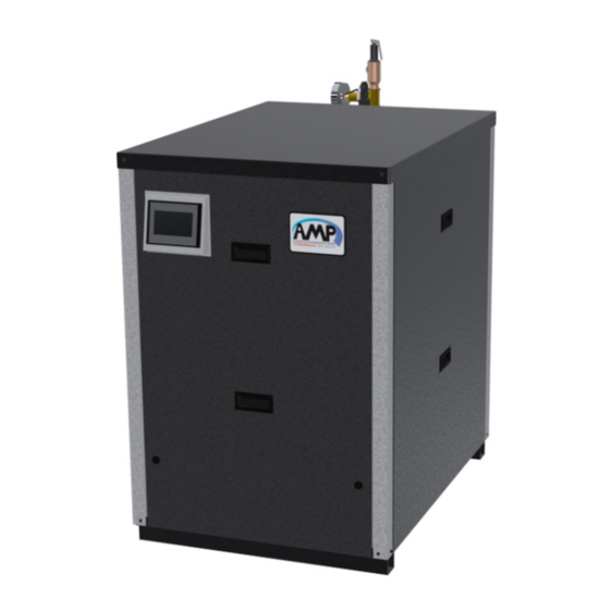
Commercial Condensing Water Heater
INSTALLATION, OPERATION, AND
MAINTENANCE MANUAL
400-1000L MBH Water Heater Indoor/Outdoor
Water Heater Models
Boiler Model:
Installation Date:
Heating Contractor:
Address:
Thermal Solutions Products, LLC
Phone: 717-239-7642
AMPW 400
AMPW 500
AMPW 650
AMPW 800
AMPW 1000L
1175 Manheim Pike, Lancaster, PA 17601
WARNING: If the information in these
instructions is not followed exactly, a fire
or explosion may result causing property
damage, personal injury or death.
Do not store or use gasoline or other
flammable vapors and liquids in the vicinity
of this or any other appliance.
WHAT TO DO IF YOU SMELL GAS
• Do not try to light any appliance.
• Do not touch any electrical switch; do
not use any phone in your building.
• Immediately call your gas supplier
from a neighbor's phone. Follow the
gas supplier's instructions.
• If you cannot reach your gas supplier,
call the fire department.
Installation and service must be performed
by a qualified installer, service agency or the
gas supplier.
Serial Number:
System Type:
Phone/Email:
PN: 110820-01
Rev. 0
Save this manual for future reference.
www.thermalsolutions.com
orders@thermalsolutions.com
Advertisement
Table of Contents

Related Manuals for AMP AMPW 1000L

Summary of Contents for AMP AMPW 1000L
- Page 1 • Immediately call your gas supplier from a neighbor’s phone. Follow the gas supplier’s instructions. Water Heater Models • If you cannot reach your gas supplier, AMPW 400 call the fire department. AMPW 500 Installation and service must be performed AMPW 650...
-
Page 2: Table Of Contents
Gas Leakage (If you detect or smell gas...) Maintenance Product Identification Label Factory Test and Inspections Disclaimers and Local Codes III. Product Rating, Specifications, and Dimensional Data IV. AMP Water Heater Component Identification Unpacking and Inspection V. Unpacking The AMP Check Equipment Installation and Operation Manual General VI. Pre-Installation and Mounting... - Page 3 Check Thermostat Operation Adjust Supply Water Temperature Testing of Controls and Safety Devices General Maintenance XIV. Service and Maintenance Monthly Inspection Annual Inspections and Service Restarting after Prolong Shutdown Troubleshooting APPENDIX A: Tables APPENDIX B: Figures APPENDIX C: Default Light-off and Modulation Rates AMPW 400-1000L I&O Manual...
-
Page 4: Hazard Definitions
Indicates a potentially hazardous situation which, if not avoided, CAUTION CAUTION may result in moderate or minor injury, or property damage. Indicates special instructions on installation, operation, or main- NOTICE NOTICE tenance which are important but not related to personal injury hazards. AMPW 400-1000L I&O Manual... -
Page 5: Read Before Proceeding
(gas valve, blower, etc.). E. Appliance Operation 1. This appliance MUST NOT be installed in any location where gasoline or flammable vapors are likely to be present or, in an environment that contains corrosive contaminants (see Table 4). AMPW 400-1000L I&O Manual... - Page 6 3. This instruction manual is an integral part of the product and must be retained by the person in charge of the appliance operation, service, and maintenance. AMPW 400-1000L I&O Manual...
-
Page 7: Product Rating, Specifications, And Dimensional Data
III. Product Rating, Specifications, and Dimensional Data AMP Water Heaters are condensing, high-efficiency, gas-fired appliances designed for use in direct domestic hot water heating systems where supply water temperature does not exceed 190°F. These water heaters have special coil type stainless steel heat exchangers, constructed, tested and stamped per Section IV of the ASME Boiler and Pressure Vessel Code, which provide maximum heat transfer and simultaneous protection against flue gas product corrosion. - Page 8 8 " 8 " 45" 2 " 2 " 8 " 4 " 2 " 4 " 4 " 8 " 8 " 8 " 4 " Front View Rear View 10" Figure 1: AMP 400-500 Dimensions AMPW 400-1000L I&O Manual...
- Page 9 8 " 4 " 45" 2 " 8 " 2 " 4 " 26 2 " 4 " 4 " 8 " 8 " 4 " 8 " Front View 10" Back View Figure 2: AMP 650-1000L Dimensions AMPW 400-1000L I&O Manual...
-
Page 10: Amp Water Heater Component Identification
21. Temperature and pressure safety relief valve entering the blower. Protects the heat exchanger from over pressure and Blower over temperature conditions. The AMP water heater Modulating blower supplying combustion air to the comes standard with a 150 PSI temperature and appliance. - Page 11 IV. AMP Water Heater Component Identification (continued) Figure 3: Component Identification AMPW 400-1000L I&O Manual...
-
Page 12: Unpacking The Amp
Please read the instructions contained in this manual carefully as they provide important information regarding the safe installation, use and servicing of this appliance. Rear intake cover Figure 4: LAMP with Outdoor Trim AMPW 400-1000L I&O Manual... -
Page 13: Pre-Installation And Mounting
Ensure all labels on the product are fully visible at all times for the purpose of maintenance and inspections. AMPW 400-1000L I&O Manual... -
Page 14: Outdoor Installation
New building construction Remodeling areas Garages with workshops B. Appliance Mounting 1. The AMP is intended for installation in an area with a floor drain, or in a suitable drain pan to prevent CAUTION CAUTION any leaks or safety relief valve discharge resulting in property damage. -
Page 15: Amp 400-1000L Stacking
VI. Pre-Installation and Mounting (continued) D. AMP 400-1000L Stacking 3. Outdoor AMP models cannot be stacked. 1. The AMP 400-1000L models may be installed in a 4. The display bracket on the top appliance can be stacked configuation. rotated for a better viewing angle of the Concert a. -
Page 16: Clearances
VI. Pre-Installation and Mounting (continued) E. Clearances NOTICE NOTICE 1. The AMP is approved for 0" clearance to combustible materials. The clearances for serviceability are This appliance is approved for zero inch clearance found in Table 5. to combustible or noncombustible material, but 2. -
Page 17: General Venting Guidelines
2% from the venting/combustion chamber and 2. The AMP is certified as a direct vent appliance but can also be used with indoor air for combustion. 8% from the air inlet portion when pressurized to operating conditions in a neutral pressure room. -
Page 18: General Termination
To avoid/minimize frost damage, extend the distance from building surfaces to vent termination end and increase the horizontal distance between adjacent vent terminations. AMPW 400-1000L I&O Manual... -
Page 19: Field Installation
17. For multiple appliance installations with horizontal E. Venting for Outdoor Installation wall terminals, maintain minimum 12 in. (300 1. The outdoor AMP ships from the factory with an mm) horizontal distance between adjacent outdoor venting kit. Kits use DuraVent FasNSeal vent terminals. - Page 20 1. Total equivalent length cannot exceed maximum equivalent length shown in Table 6. 2. Combustion air and vent terminations do not count towards total equivalent length. NOTICE NOTICE Do not exceed maximum vent/combustion air system length. AMPW 400-1000L I&O Manual...
- Page 21 ACFM @ 35% SCFM @ 35% ACFM @ 35% SCFM @ 35% Model Excess Air, 180 Excess Air, 60 Excess Air, 180 Excess Air, 60 1000L Note: Flow rates are based on the combustion of natural gas. AMPW 400-1000L I&O Manual...
- Page 22 IASPP06 2ZDES6 Use of cellular core PVC (ASTM F891), cellular core CPVC, or Radel® (poly- phenylsulfone) in non-metallic venting systems is prohibited. NOTICE NOTICE Covering non-metallic vent pipe and fittings with thermal insulation is pro- hibited. AMPW 400-1000L I&O Manual...
- Page 23 VII. Venting (continued) Figure 8: Vent Terminal Clearances AMPW 400-1000L I&O Manual...
- Page 24 In accordance with the current CSA B149.1, Natural Gas and Propane Installation Code In accordance with the current ANSI Z223.1/NFPA 54, National Fuel Gas Code If locally adopted installation codes specify clearances different than those illustrated, then the most stringent clearance shall prevail. AMPW 400-1000L I&O Manual...
- Page 25 In accordance with the current CSA B149.1, Natural Gas and Propane Installation Code In accordance with the current ANSI Z223.1/NFPA 54, National Fuel Gas Code If locally adopted installation codes specify clearances different than those illustrated, then the most stringent clearance shall prevail. AMPW 400-1000L I&O Manual...
-
Page 26: General Termination
Atmospheric venting is prohibited. combustion air. Recirculation of the flue products can cause damage to property or the appliance. AMPW 400-1000L I&O Manual... - Page 27 24in. (610mm) MAX 24 in. (610mm) MIN TO WALL (TYP) 12in. (305mm) MIN. ABOVE HIGHEST ANTICIPATED SNOW LEVEL 12in. (305mm) MIN. ABOVE COMBUSTION AIR TERMINAL 24 in. (610mm) MIN Figure 10: Horizontal Sidewall Termination Figure 11: Vertical Roof Termination AMPW 400-1000L I&O Manual...
-
Page 28: Terminal Installation
24in. (610mm) MAX good repair (sealed, painted, etc.). TO WALL (TYP) Do not allow low spots in the vent where con- densate may pool. Use specified vent and combustion air pipe diameters. All vent and combustion air piping must be sealed and airtight. Alteration of the appliance vent connection is prohibited. Figure 12: Snorkel Termination AMPW 400-1000L I&O Manual... -
Page 29: Flexible Polypropylene Venting
3. Maximum equivalent vent length of flexible polypropylene liner is 48 ft. (14.6 m). Installation of a polypropylene vent system should adhere to the vent manufacturer's installation in- structions supplied with the vent system. AMPW 400-1000L I&O Manual... - Page 30 Do not insulate polypropylene vent pipes. Excessive heat could cause premature vent pipe failure. Figure 13: Flexible Vent in Masonry Chimney with Separate Combustion Air Intake AMPW 400-1000L I&O Manual...
-
Page 31: Optional Room Air For Combustion
Not less than the sum of the areas of all vent distillates, detergents, volatile vapors or other connectors in the space. chemicals must not be present in the boiler room. If any of these contaminants are present, severe corrosion and failure will result. AMPW 400-1000L I&O Manual... -
Page 32: Multiple Appliance Terminations
24 in. (610mm) MIN. 24 in. (610mm) MIN. 24 in. (610mm) MIN. 24in. (610mm) MAX. TO WALL (TYP) Horizontal Sidewall 24 in. (610mm) MIN. 24 in. (610mm) MIN. Vertical Roof Figure 14: Multiple Appliance Direct Vent Termination AMPW 400-1000L I&O Manual... -
Page 33: Removing Existing Appliance
Propane Installation Code, CAN/CSA B149.1. Resizing of any portion of the common venting system, should be done in accordance with the National Fuel Gas Code, ANSI Z223.1/NFPA 54 and/ or the Natural Gas and Propane Installation Code, CAN/CSA B149.1. AMPW 400-1000L I&O Manual... - Page 34 2. EXEMPTIONS: The following equipment is exempt from 248 CMR 5.08(2)(a) 1 through 4: a. The equipment listed in Chapter 10 entitled “Equipment Not Required To Be Vented” in the most current edition of NFPA 54 as adopted by the Board; and AMPW 400-1000L I&O Manual...
-
Page 35: Condensate Disposal
Use continuous Teflon, high temperature silicone tubing, or other tubing material compatible with flue gas condensate for condensate piping. c. Do not route or terminate the condensate drain line in areas subject to freezing temperatures. AMPW 400-1000L I&O Manual... -
Page 36: Common Condensate Pump/Sump
2. If a common sump is used, individual drain lines 107860-09 107886-10 should be constructed, using material listed above, 107860-09 107886-10 such that one drain cannot back feed into another drain. 1000L 107860-06 107886-06 3. Do not manifold condensate and vent drains together. AMPW 400-1000L I&O Manual... -
Page 37: Water Piping
IX. Water Piping NOTICE NOTICE The AMP water heater is considered to be a circulating water heater or hot water supply boiler. This Product will operate most efficiently and reliably when paired with one or more storage tanks. Failure to properly pipe appliance may result in A. - Page 38 2" pipe nipple, close 2" X 2" X 3/4" reducing tee 3/4" pipe nipple, close 3/4" X 1/2" reducing tee T&P relief valve 1/2" pipe nipple x 1-1/2" Long 1/2" full coupling T&P gauge Water flow switch AMPW 400-1000L I&O Manual...
-
Page 39: Standard Piping Components
If the Storage tanks require their own T&P relief expansion tank must be replaced, consult the valve installed according to the manufacturers expansion tank manufacturer’s literature for proper... -
Page 40: Scalding
Figure 19. The AMP heat exchanger is made from stainless 3. Scalding can occur at temperatures above 125 0F. steel tubular double coil having relatively nar- Young Children, disabled, and elderly are most at row waterways. -
Page 41: Water Quality
8.5. than 5 ppm and the level of chloride is less than 1000 ppm. a. The AMP is not designed for the heating of swimming pool water. 6. Before connecting the appliance, insure the system is free of impurities, grease, sediment, construction Table 21: Absolute Water Flow Rates... -
Page 42: Temperature Rise And Heat Exchanger Head Loss
IX. Water Piping (continued) F. Temperature Rise and Heat Exchanger Head Loss 1. The AMP heat exchanger adds pressure drop to the system which must be accounted for in the design of the piping configuration and pump selection. 2. The system should be designed to maintain the operating water flow rate shown in Table 20 while never exceeding the range of absolute flow rates shown in Table 21. -
Page 43: Pump Selection
NOTE: The total loss includes 50 ft of pipe, 8 elbows, and 4 Valves. It is the installer's or system designer's responsibility to account for differ- NOTICE NOTICE ences in the circulation loop. Length, pipe diameter, elbows, and valves all contribute to the total pressure drop in the loop. AMPW 400-1000L I&O Manual... -
Page 44: Water Piping Diagrams
Expansion Tank Check Valve Mixing Valve Union Hot Water Supply Thermometer T & P Relief Valve Strage Tank Water Heater Circulator Isolation Valve Y-Strainer 1. These are suggested piping configurations. It is the installer's responsibility to conform to local codes and ordinances for additional requirements. - Page 45 3. Some piping components cannot be supported by the pipping. Refer to the manufactures' installation instructions. NOTICE NOTICE 4. Circulation pump must be sized to overcome the pressure drop across the entire loop. 5. Erosion could occur if common piping is undersized. AMPW 400-1000L I&O Manual...
- Page 46 3. Some piping components cannot be supported by the pipping. Refer to the manufactures' installation instructions. NOTICE NOTICE 4. Circulation pump must be sized to overcome the pressure drop across the entire loop. 5. Erosion could occur if common piping is undersized. AMPW 400-1000L I&O Manual...
-
Page 47: Gas Piping
For testing at 1/2 psig (3.4 kPa) or less, isolate the appliance from gas supply piping by closing the manual shutoff valve on the appliance. Figure 21: The AMP 400-1000L Gas Connection NOTICE NOTICE 8. Locate leaks using approved combustible gas non- corrosive leak detector solution. - Page 48 *1 CFH of LP gas is approximately equal to 2.5 MBH; contact your gas supplier for the actual heating value of your gas. Table 26: Equivalent Lengths of Standard Pipe Fittings & Valves (ft) Valves (Screwed) - Fully Open Screwed Fittings...
-
Page 49: Gas Pressure Switches
Older or non-lock-up type regulators may result in nuisance lockouts on gas pressure drops or spikes. The AMP and all other appliances must be firing at maximum capacity to properly measure the inlet gas pressure. -
Page 50: Electrical
1. 1. Route all field connections through conduits into Route all field connections through conduits into Verify Proper operation after servicing. the rear control box. the rear control box. AMPW 400-1000L I&O Manual... -
Page 51: System And Circulation Pump Wiring
NEUTRAL GROUND SYSTEM PUMP OPTIONAL DOMESTIC HOT WATER PUMP MAX. 5.6A TOTAL PUMP BOILER PUMP CURRENT DRAW COMBUSTION AIR DAMPER 6.3A, SLOW BLOW (IF USING 5mm X 20mm FUSE ROOM AIR) Figure 23: 120 VAC Connections PCB AMPW 400-1000L I&O Manual... - Page 52 XII. Electrical (continued) Figure 24: Low Voltage Connections PCB AMPW 400-1000L I&O Manual...
- Page 53 COMBUSTION AIR DAMPER AND PROVING SWITCH ARE REQUIRED IF USING ROOM AIR FOR COMBUSTION WITH MOTORIZED DAMPER(S) OR LOUVER(S). ENERGY MANAGEMENT SYSTEM WIRING CAN BE DONE WITH RJ45 PLUGS OR USING SCREW TERMINALS A, B AND C LABELED 'EMS (DELTA ONLY)'. Figure 25: AMP 400-1000L Wire Schematic AMPW 400-1000L I&O Manual...
- Page 54 System System Pump L Pump N System Pump LWCO P3-12 L2-1 L2-3 P3-2 24V Transformer Figure 26: AMP 400-1000L Wire Diagram 24V Fuse, F3 24V Transformer Control Panel Size 400-500: 1.6A Slow Blow Ground Screw P8-8 L3-1 L3-2 Igniter Flame Sensor...
- Page 55 Peer-to-Peer and EMS J8-8 Outlet/ J8-9 Supply Sensor J8-10 J9-4 Flue Gas J9-5 Sensor J9-6 J10-7 Outdoor P8-11 J10-8 Sensor P8-3 J8-11 Header/ Tank P8-9 Sensor J8-6 Remote P8-1 4-20mA J9-1 P8-2 J9-2 Sensor P8-10 Wire Diagram (continued) AMPW 400-1000L I&O Manual...
-
Page 56: System Start-Up
Table 28. Each AMP Series appliance is tested at the factory and adjustments to the air fuel mixture are nor- d. Reset high and low gas pressure switches by pressing the reset button. - Page 57 3. Tourner la chaudière externe manuelle poignée en clapet à gaz dans le 3. Turn the external boiler manual gas valve handle clockwise sens des aiguilles d'une montre pour fermer l'offre de gaz. to close gas supply. 101607-03 Figure 27: Operating Instructions AMPW 400-1000L I&O Manual...
-
Page 58: Combustion Air/Fuel Adjustment
Refer to Figure 28 or Figure 29 for location of Offset Screw (adjustment not normally required) throttle screw. Verify CO air free is less than 200 ppm. Figure 28: AMP 650-1000L Gas Valve Adjustment VALVE COIL (V2) INLET GAS PRESSURE TAP (P1) WITH INTERNAL SCREW... -
Page 59: Field Conversion Of Gas Type
111545-02 111544-02 6. Fill out the gas conversion labels included with the 111545-03 111544-03 appliance (Order part number 110301-01 if not 111545-04 111544-04 included). Follow the instructions included with the 1000L 111545-05 111544-05 label for placement. AMPW 400-1000L I&O Manual... -
Page 60: Pump Control
Low Water Level. pressing the reset button. down the main burner. Reduce the water flow rate with Water Flow Adjust manual valve to normal a manual shutoff valve until the Low Water Flow Switch position. appliance shuts down. AMPW 400-1000L I&O Manual... -
Page 61: Service And Maintenance
• If contact with skin: Wash affected area gently with soap and water. Seek immediate medical attention if irritation persists. • If breathing difficulty develops: Leave the area and move to a location with clean fresh air. Seek immediate medical attention if breathing difficulties persist. • Ingestion: Do NOT induce vomiting. Drink plenty of water. Seek immediate medical attention. AMPW 400-1000L I&O Manual... -
Page 62: General Maintenance
Wiring errors can cause improper and dangerous operation. Verify proper operation after servicing. NOTICE NOTICE To reduce lime scale buildup and prolong the life of the appliance, closely monitor pH, chloride, total dissolved solids, and water hardness levels. AMPW 400-1000L I&O Manual... - Page 63 Never jump out or bypass any safety or operating control or component. Interior of the venting system must be inspected and clean before the initial startup and should be inspected periodically for any obstructions. AMPW 400-1000L I&O Manual...
- Page 64 Slide the control box out. ii. Do not spray burner, combustion chamber divider, or burner door insulations. e. The burner door, blower, and mixer assembly can be pulled out of the appliance jacket as shown in Figure 32. AMPW 400-1000L I&O Manual...
-
Page 65: Restarting After Prolong Shutdown
Control manual on how to navigate the Limit String Status screen which shows an active safety limit status and for an in-depth guide to all the possible lockouts as well as recommended corrective actions to restore operation. AMPW 400-1000L I&O Manual... -
Page 66: Appendix A: Tables
APPENDIX A: Tables I. Hazard Definitions II. Read Before Proceeding Table 1: AMP Water Heater Ratings III. Product Rating, Specifications, and Dimensional Data Table 2: AMP Water Heater Specifications Table 3: Appliance Connection Sizes IV. AMP Water Heater Component Identification V. Unpacking The AMP Table 4: Corrosive Combustion Air Contaminants VI. Pre-Installation and Mounting Table 5: AMP 400-1000L Clearances Table 6: Vent and Combustion Air Pipe Diameters and Maximum Lengths VII. Venting Table 7: Equivalent lengths of Vent and Combustion Air Components Table 8: Vent and Combustion Air Equivalent Length Calculation Worksheet Table 9: Recommended Venting Configurations and Material Options Table 10: Combustion Air and Flue Gas Flow Rates Table 11: Approved Vent Manufacturers and Materials Table 12: Stainless Steel Vent Terminations Table 13: Polypropylene Vent Terminations Table 14: Direct Vent Terminal Clearances Table 15: Other than Direct Vent Terminal Clearances Table 16: Condensate Neutralizer Kit... -
Page 67: Appendix B: Figures
APPENDIX B: Figures I. Hazard Definitions II. Read Before Proceeding Figure 1: AMP 400-500 Dimensions III. Product Rating, Specifications, and Dimensional Data Figure 2: AMP 650-1000L Dimensions Figure 3: Component Identification IV. AMP Water Heater Component Identification Figure 4: LAMP with Outdoor Trim V. Unpacking The AMP Figure 5: AMP 400-1000L Stacking Brackets and Dislplay Rotation VI. Pre-Installation and Mounting Figure 6: Side by Side installation Figure 7: Outdoor Venting Installation VII. Venting Figure 8: Vent Terminal Clearances Figure 9: Slopped Roof Termination Figure 10: Horizontal Sidewall Termination Figure 11: Vertical Roof Termination Figure 12: Snorkel Termination Figure 13: Flexible Vent in Masonry Chimney with Separate Combustion Air Intake Figure 14: Multiple Appliance Direct Vent Termination Figure 15: Condensate Drain Assembly VIII. Condensate Disposal... -
Page 68: Appendix C: Default Light-Off And Modulation Rates
1900 2400 Maximum Light-off (RPM) 3600 2600 2200 2600 2000 2600 Minimum Light-off (RPM) 3000 2200 1700 2200 1700 2200 Factory Default RPM NOTE: To maintain rate in maximum vent length application, contact factory for assistance. AMPW 400-1000L I&O Manual... - Page 69 Notes AMPW 400-1000L I&O Manual...
- Page 70 This page is intentionally left blank. AMPW 400-1000L I&O Manual...
- Page 71 Any damage caused by water side clogging due to dirty systems, corrosion products from the system, or improperly maintained water conditions. AMPW 400-1000L I&O Manual...
- Page 72 Thermal Solutions Product, LLC Lancaster, PA 17604-3244 Phone: 717-239-7642 orders@thermalsolutions.com www.thermalsolutions.com...
Need help?
Do you have a question about the AMPW 1000L and is the answer not in the manual?
Questions and answers