Table of Contents
Advertisement
Quick Links
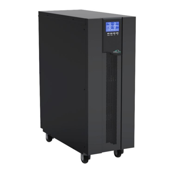
Uninterruptible Power Supply
UQ11 6-10 KVA
UQ31 10-20KVA
İÇERENKÖY MAH.
ÇANKIRI SK. NO:1/1
ATAŞEHİR – İSTANBUL
TEL : +90 216 574 1 574
FAX: +90 216 574 71 14
E-MAIL :
www.powerguard.com.tr
USER MANUAL
info@powerguard.com.tr
İÇERENKÖY MAH.
ÇANKIRI SK. NO:1/1
ATAŞEHİR – İSTANBUL
TEL : +90 216 574 1 574
FAX: +90 216 574 71 14
E-MAIL :
info@powerguard.co
www.powerguard.com.tr
Advertisement
Table of Contents

Related Manuals for PowerGuard UQ11


Summary of Contents for PowerGuard UQ11
- Page 1 ÇANKIRI SK. NO:1/1 TEL : +90 216 574 1 574 ATAŞEHİR – İSTANBUL FAX: +90 216 574 71 14 TEL : +90 216 574 1 574 E-MAIL : info@powerguard.co FAX: +90 216 574 71 14 www.powerguard.com.tr E-MAIL : info@powerguard.com.tr www.powerguard.com.tr...
- Page 2 Please comply with all warnings and operating instructions in this manual and on the unit strictly. Save this manual properly. Do not operate this unit before reading through all safety information and operating instructions carefully.
-
Page 3: Table Of Contents
TABLE OF CONTENTS 1.Safety and EMC Instructions 1.1 Installation 1.2 Operation 1.3 Maintenance, servicing and faults 1.4 Transport 1.5 Storage 1.6 Standards 2. Description of commonly used symbols 3. Introduction 3.1 System and m odel description 3.2 Product Specification and Perform ance 4. - Page 4 10. Operating mode for all models 10.1 No Output mode 10.2 Bypass mode 10.3 Line mode 10.4 Battery mode / Battery Test mode 10.5 Parallel mode 10.6 Warning mode 10.7 Fault mode 11. Setting by LCD Module 12. Communication Port 12.1 RS232 Interface 12.2 Intelligent slot 12.3 AS400 Interface(Option)
-
Page 5: Safety And Emc Instructions
1.Safety and EMC instructions Please read carefully the following user manual and the safety instructions before installing the unit or using the unit! 1.1 Installation ★ Condensation may occur if the UPS is moved directly from a cold to a warm environment. The UPS must be absolutely dry before being installed. -
Page 6: Operation
★ For three-phase equipment connection to an IT power system, a four-pole device which disconnect all phase conductors and the neutral conductor should be provided in the building wiring installation. ★ This is permanently connected equipment , it must be installed by qualified maintenance personnel. -
Page 7: Transport
★ Before carrying out any kind of service and/or maintenance, please disconnect the batteries. Verify that no current is present and no hazardous voltage exists in the capacitor or BUS capacitor terminals. ★ Batteries must be replaced only by qualified personnel. ★... -
Page 8: Storage
1.5 Storage ★ The UPS must be stockpiled in the room where it is ventilated and dry. 1.6 Standards * Safety IEC/EN 62040-1-1 * EMI Conducted Emission....:IEC/EN 62040-2 Category C3 Radiated Emission.......:IEC/EN 62040-2 Category C3 *EMS ESD..........:IEC/EN 61000-4-2 Level 4 RS......... -
Page 9: Description Of Commonly Used Symbols
2. Description of commonly used symbols Some or all of the following symbols may be used in this manual. It is advisable to familiarize yourself with them and understand their meaning: -5-... -
Page 10: Introduction
3. Introduction 3.1 System and model description This Online Series is an uninterruptible power supply incorporating double-conversion technology. It provides perfect protection specifically for computer equipment, communication systems to computerized instruments. Its true online double-conversion design eliminates all mains power disturbances. -
Page 11: Product Specification And Performance
3.2 Product Specification and Performance 1) General Specification 6KT 6KT-XL 10KT 10KT-XL 3C 10KT-XL 3C15KT-XL 3C20KT-XL Model 6KVA/4.2KW 10KVA/7KW 10KVA/7KW 15KVA/10.5KW 20KVA/14KW Power Rating 50/60 50/60 50/60 50/60 50/60 Frequency (Hz) (176-276)V (176-276)V (304-478)V (304-478)V (304-478)V Voltage Input 32A max. 50A max 50A max 75A max... - Page 12 3) Operating Environment Temperature Humidity Altitude Storage temperature 0°C-40°C <95% <1000m 0°C-40°C Note: if the UPS is installed or used in a place where the altitude is above than 1000m, the output power must be derated in use, please refer to the following: Altitude (M) 1000 1500 2000 2500 3000 3500 4000 4500 5000 Derating...
-
Page 13: Display Panel
4. Display Panel Display Panel Button Function Turn on UPS system: By pressing the ON button “I” the UPS system is turned on. ON Button Deactivate acoustic alarm: By pressing this button an acoustic alarm can be deactivated. When mains power is normal, the UPS system switches to Bypass mode by pressing OFF button “... - Page 14 LCD Display Display Function Input Information Indicates the input voltage value, which could be displayed from 0 to 999V Indicates the frequency value of input voltage, which could be displayed from 0 to 99Hz Indicates the input voltage is higher than the SPEC range, if the voltage is normally, it can not be displayed Indicates the input voltage is lower than the SPEC range, if the voltage is normally, it can not be displayed...
- Page 15 Indicates the UPS output is short and the UPS would shut down Indicates the load is over the SPEC range Battery Information Indicates the battery voltage value, which could be displayed from 0 to 999Vdc Indicates the battery capacitance percent, which could be displayed from 0 to 199% Indicates the battery is over charged, and the UPS would be switched to Battery mode...
-
Page 16: Installation
5. Installation The system may be installed and wired only by qualified electricians in accordance with applicable safety regulations! 5.1 Unpacking and Inspection 1) Unpack the packaging and check the package contents. The shipping package contains: A UPS ● A user manual ●... - Page 17 2. Installation Installation and wiring must be performed in accordance with the local electric code and the following instructions by professional personnel. For safety, please cut off the mains power switch before installation. The battery breaker also needs to be cut off if it is a long backup time model (“...
- Page 18 After having completed the installation, make sure the wiring is correct. Please install the output breaker between the output terminal and the load, and the breaker should with leakage current protective function if necessary. To connect the load with the UPS, please turn off all the loads first, then perform the connection and finally turn on the loads one by one.
- Page 19 Input and output Terminal Block wiring diagram of 3C10KT-XL Important notes: If the UPS is used in single mode, JPI and JP2 must be connected by 10AWG(6mm ). If the UPS is used in parallel mode, JP1 and JP2 must be removed. Input and output Terminal Block wiring diagram of 3C15KT-XL/3C20KT-XL Important notes: If the UPS is used in single mode, JPI and JP2...
-
Page 20: Operating Procedure For Connecting The Long Backup Time Model Ups With The External Battery
5.3 Operating procedure for connecting the long backup time model UPS with the external battery 1. The nominal DC voltage of external battery pack is 240VDC. Each battery pack consists of 20 pieces of 12V maintenance free batteries in series. To achieve longer backup time, it is possible to connect multi-battery packs, but the principle of “same voltage, same type”... -
Page 21: Parallel Operation
To complete the connection by plugging the connector of the external battery cable into the external battery socket of the UPS. Do not attempt to connect any loads to the UPS now. You should connect the input power wire to the right position first. And then set the breaker of the battery pack in the “ON”... - Page 22 2. Parallel installation Users need to opt a standard 25-pin communication cable, which should have 25 cores, corresponding stitches and shield, as the UPS parallel cable. The length of the parallel cable is appropriate to be less than 3 m. Strictly follow the stand-alone wiring requirement to perform the input wiring of each UPS.
- Page 23 -19-...
- Page 24 -20-...
- Page 25 -21-...
- Page 26 3. Operation and maintenance 1) To perform the general operation, follow the stand-alone operating requirement. 2) Startup: The units transfer to INV mode simultaneously as they start up sequentially in Line mode. 3) Shutdown: the units shut down sequentially in INV mode. When the last one completes the shutdown action, each unit will shut down the inverter simultaneously and transfer to Bypass mode.
-
Page 27: Operation
6. Operation 6.1 Operation Mode 1. Turn on the UPS with utility power supplied (in Line mode) 1) After you make sure that the power supply connection is correct, and then set the breaker of the battery pack in the “ON” position (this step only for long backup time model), after that set the input breaker in the “ON”... -
Page 28: Parallel Operation
2) Upon completion of the above to turn it off, output of electric current of the UPS is still present. In order to cut off the output from the UPS, simply cut off the utility power supply, a few seconds later, there are not any display is shown on the display panel and no voltage output is available from the UPS output. - Page 29 block. Remove the maintenance cover board of each UPS and set the maintenance switch from “UPS” to “BPS”. Remove the cover board of the parallel port on the UPS, connect each UPS one by one with the parallel cable, screw the cover board of the parallel port back again.
- Page 30 3. How to join a new UPS: 1) Before joining a new UPS, user need to prepare the input and output wires, the output breaker, and the parallel cable. 2) Turn off the input and output breakers of the new unit. Connect the input wires, output wires and battery wires.
- Page 31 9) Close the input breakers of all of the UPS (including the new UPS) in the parallel system. After all of the UPS transfer to the Bypass mode, screw the maintenance cover board back again. 10) Turn on each UPS in turn and observe their display. Make sure that each UPS displays normal and all the UPSs transfer to the INV mode together.
- Page 32 3) Press the others UPSs’s OFF button. After all of them transfer to the Bypass mode, remove the cover board of each UPS and set the maintenance switch from “UPS” to “BPS” and then turn off the input breaker of each UPS. 4) After you remove one UPS, you need to connect the short connection wire of the JP1 and JP2 located on the Terminal block of the UPS if the remained UPS system only remain one...
-
Page 33: Backup Time For The Standard Model
3) When UPS combine system work at inverter model, please do not operate any UPS maintain switch. 6.3 Backup time for the standard model The backup time of the long backup time model is dependent on the external battery pack capacity and the load level as well as other factors. -
Page 34: Battery Maintenance
7. Battery Maintenance This series UPS only requires minimal maintenance. The battery ● used for standard models are value regulated sealed lead-acid maintenance free battery. These models require minimal repairs. The only requirement is to charge the UPS regularly in order to maximize the expected life of the battery. -
Page 35: Notes For Battery Disposal And Battery Replacement
8. Notes for Battery Disposal and Battery Replacement 1) Before disposing of batteries, remove conductive jewelry such as necklace, wrist watches and rings. 2) If it is necessary to replace any connection cables, please purchase the original materials from the authorized distributors or service centers, so as to avoid overheat or spark resulting in fire due to insufficient capacity. -
Page 36: Trouble Shooting
9. Trouble Shooting Problem Possible cause Solution Make sure the UPS is not overloaded; the air vents are not The Fault code is blocked and the ambient The UPS transfers to “08”, and the temperature is not too high. Wait fault mode due to buzzer beeps for 10 minutes for the UPS to... - Page 37 Check the battery. If the battery is damaged, replace the battery The Fault code is Battery low or battery immediately and ensure that the “11”, the UPS not connected. battery breaker is in “ON” beeps continuously. position. The utility power is Please contact the distributor or normal, but the Maintain switch loose...
-
Page 38: Operating Mode For All Models
10. Operating mode for all models The different codes could be displayed on the LCD screen corresponding to their own operating modes, and they are illustrated as the follow: Operating mode Code Operating mode Code Mode Code Table No Output mode Battery mode Bypass mode Battery test mode... -
Page 39: Bypass Mode
No Output mode The UPS have no output in the mode. 10.2 Bypass mode The LCD display in Bypass mode is shown in the following diagram. The information about the utility power, the battery, the UPS output and the load could be displayed. The operating mode code of the UPS is “01”. -
Page 40: Line Mode
The UPS does not have the backup function when it is in Bypass mode. The power used by the load is supplied from the utility power via internal filter. 10.3 Line mode The LCD display in Line mode is shown in the following diagram. The information about the utility power, the battery, the UPS output and the load could be displayed. -
Page 41: Battery Mode / Battery Test Mode
The power capacity of the AC generator should be at least ● twice of the UPS capacity. 10.4 Battery mode / Battery Test mode The LCD display in Battery mode is shown in the following diagram. The information about the utility power, the battery, the UPS output and the load could be displayed. -
Page 42: Parallel Mode
The display of battery test mode is same as Battery mode, but “H” and “L” would not be shown unless the input line voltage is higher or lower than the SPEC range during the time of battery test. The operating mode code of the UPS is “03” in Battery mode, and the code is “04”... -
Page 43: Fault Mode
Warning mode (Fan Error) 10.7 Fault mode The LCD display in fault is shown in the following diagram. The information about the utility power, the battery, the UPS output and the load could be displayed. The symbol “MODE” not be shown and the symbol “FAULT”... - Page 44 Note: If mode code is “10”, it means that “Inner Communication Fault”, and all the information of the UPS have not be shown except fault code information, like the following diagram. Communication Fault mode -40-...
-
Page 45: Setting By Lcd Module
11. Setting by LCD Module The output voltage rating and frequency rating and bypass state could be set directly through LCD Display. The output voltage rating could be set to 208V , 220V, 230V and 240V. The output frequency rating could be set to 50Hz and 60Hz. - Page 46 STEP 1: One flickering black round dot would appear in front of ” after pressing the Select button. “208V STEP 2: The flickering dot would move to the front of “230V ” after pressing the Select button two times again. -42-...
- Page 47 STEP 3: The dot in the front of 230V would turn to flickerless after pressing the Enter button, and the flickering dot would move to the next “240V ”. STEP 4: The output voltage rating have been modified to “230V ”, and UPS work in Bypass mode.
- Page 48 STEP 5: The output voltage would be 230V after the UPS is turned -44-...
-
Page 49: Communication Port
12. Communication Port 12.1 RS232 Interface The following is the pin assignment and description of DB-9 connector. Pin # Description Output Input Input 12.2 Intelligent slot This series is equipped with an intelligent slot for Webpower (optional accessory) or other optional card to achieve remote management of the UPS through internet / intranet. - Page 50 DB-9 Interface of AS400 communication protocol -46-...
-
Page 51: Software For All Models
13. Software for all models Free Software Download – WinPower WinPower is a brand new UPS monitoring software, which provides user-friendly interface to monitor and control your UPS. This unique software provides safely auto shutdown for multi-computer systems while power failure. With this software, users can monitor and control any UPS on the same LAN no matter how far from the UPSs. -
Page 52: Appendix 1:The Corresponding Form Of The Lcd Display
Appendix 1:The Corresponding Form of the LCD Display LCD Code Operating state Alarm warning Display No Output mode None Beep once every Bypass mode 2 min. Line mode None 0~20% Battery capacity Beep once every Battery 21%~100% Battery Beep once every mode capacity 4 sec... -
Page 53: Appendix 2:Rear Panel
Appendix 2:Rear Panel Back view of 6KVA Back view of 6KVA-XL Back view of 10KVA Back view of 10KVA-XL -49-... - Page 54 Back View of 31- 10KVA Back View of 31-20KVA -50-...
- Page 55 -51-...
Need help?
Do you have a question about the UQ11 and is the answer not in the manual?
Questions and answers