Table of Contents
Advertisement
Service Manual
This service information is designed for experienced repair technicians only and is not designed for use by the general public. It does not
contain warnings or cautions to advise non-technical individuals of potencial dangers in attempting to service a product. Products
powered by electricity should be serviced or repaired only by experienced professional technicians. Any attempt to service or repair the
product or products deal within this service information by anyone else could result in serious injury or death.
There are special components used in this equipment which are important for safety. These parts are marked
Schematic Diagrams, Circuit Board Diagrams, Explorer Views and Replacement Parts List. It is essential that these
critical parts should be replaced with manufacturer´s specified parts to prevent shock, fire or other hazards. Do not
modify the original design without permission of manufacturer.
Warning
IMPORTANT SAFETY NOTICE
ORDER No. PCZ1404084CE
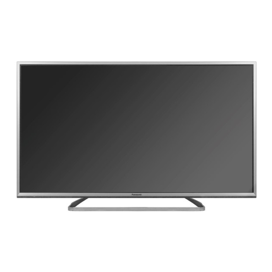
LCD Television
TX-42AS750E
TX-42ASW754
TX-42ASR750
LA51 Chassis
© Panasonic Corporation 2014.
Unauthorized copying and
distribution is a violation of law.
in the
Advertisement
Table of Contents

Summarization of Contents
Safety Precautions
General Guide Lines
Guidelines for safe servicing, part replacement, and safety checks.
Touch-Current Check
Procedure for measuring touch currents to prevent electrical shock hazards.
Lead Free Solder Information
Suggested Lead Free Solder
Recommendations for suitable types of lead-free solder for repair work.
Service Navigation
Chassis Board Layout
Diagram showing the location of main circuit boards: A-Board, P-Board, K-Board, GK-Board.
Service Hints
How to Remove the Backcover
Step-by-step instructions for safely removing the TV's back cover.
Technical Description
KEY Specification for Digital Content Protection
Details on key generation and features for DTCP-IP, HDCP2, Netflix, and Widevine.
USB HDD Recording Function
Information on recording digital TV programs to USB HDD and related key binding.
Setting Inspection
Voltage Confirmation
Table listing test points and expected voltages for A-board and P-board components.
Service Mode Function
How to Enter Service Mode
Instructions for accessing the service mode using the remote control and unit buttons.
How to Exit Service Mode
Procedure to exit the service mode.
Service Adjustments
Service Menu Key Command
Explanation of remote control buttons used for navigating and adjusting service menu options.
White Balance Adjustment (WB-ADJ)
Procedures for adjusting white balance settings using gain and center values.
Option Settings
Configuration options for various TV features accessible via the service menu.
Service Tool Mode
How to Access Service Tool Mode
Steps to access the Service Tool Mode from the main service menu.
Display of SOS History
Information on interpreting the SOS History codes indicated by power LED blinking.
Power ON Time, On/Off
Displaying and understanding cumulative power-on time and on/off switching counts.
Hotel Mode
Hotel Mode Purpose
Explains the function of Hotel Mode for restricting TV features in hospitality environments.
Access Command for Hotel Mode Setup
Sequence of button presses to enter the Hotel mode setup menu.
Hotel Mode Setup Menu Explanation
Detailed explanation of various settings within the Hotel Mode menu.
USB Data Copy
Data Copy for Board Replacement
Procedure to copy TV data to USB for A-board replacement.
Data Copy for Hotel Installation
Procedure to copy TV data to USB for mass installation in hotels.
USB Memory Preparation
Steps to prepare a USB memory stick with a startup file for data copying.
Self Check Procedure
How to Access Self Check
Methods to access self-check indication and factory shipment setting.
How to Exit Self Check
Procedure for exiting the self-check mode.
LCD Panel Test Mode
LCD Panel Test Mode Purpose
Objective of the LCD Panel Test Mode for diagnosing display failures.
How to Enter LCD Panel Test Mode
Steps to activate the LCD Panel Test Mode using remote control buttons.
How to Exit LCD Panel Test Mode
Procedure for turning off the TV to exit the LCD Panel Test Mode.
How to Confirm Failure Cause
Method for determining the cause of failure based on test pattern display.
Block Diagrams
Block Diagram (1 of 2)
Shows the functional blocks and interconnections of the TV's internal components.
Block Diagram (2 of 2)
Continues the block diagram illustrating the TV's internal component interconnections.
Schematic Diagrams
Schematic Diagrams Notes
Notes on component symbols, safety, and measurement conventions used in schematics.
A-BOARD Schematic Diagrams
Detailed schematic diagrams for the A-BOARD, presented in multiple parts.
P-BOARD Schematic Diagrams
Detailed schematic diagrams for the P-BOARD, presented in multiple parts.
K-BOARD Schematic Diagram
Schematic diagram for the K-BOARD.
GK-BOARD Schematic Diagram
Schematic diagram for the GK-BOARD.
Conductor Views
A-BOARD Conductor Views
Top and bottom views of the A-board PCB layout with component locations.
P-BOARD Conductor Views
Top and bottom views of the P-board PCB layout with component locations.
GK-BOARD Conductor Views
Top and bottom views of the GK-board PCB layout with component locations.
K-BOARD Conductor View
View of the K-board PCB layout with component locations.


Need help?
Do you have a question about the TX-42ASR750 and is the answer not in the manual?
Questions and answers