Table of Contents
Advertisement
Advertisement
Table of Contents

Related Manuals for Wood-mizer MD500

Summary of Contents for Wood-mizer MD500
- Page 1 MD400, MD500 Chip Extractor: Safety, Operation, Maintenance, and Parts Manual MD400EA3U MD400EA3U-SYS MD400EB3U MD400EB3U-SYS MD500EB5U MD500EB5U-SYS REV B1.00 - Current Safety is our #1 concern! Form #2358-US WARNING! Read and understand this manual before using this machine.
- Page 2 Active Patents assigned to Wood-Mizer, LLC Wood-Mizer, LLC has received patents that protect our inventions which are a result of a dedication to research, innovation, development, and design. Learn more at: woodmizer.com/patents ©2020 Wood-Mizer LLC Printed in the United States of America, all rights reserved. No part of this manual may be reproduced in any form by...
-
Page 3: Table Of Contents
SECTION 2 GENERAL SAFETY Safety Symbols ..................2-1 Safety Instructions.................. 2-1 SECTION 3 SPECIFICATIONS Specifications of MD400 and MD500 chip extractors ......3-1 Overall dimensions ................3-3 SECTION 4 SETUP Attaching the Chip Extractor ..............4-1 Optional Cyclone Twin Bag Collector Assembly........4-1 SECTION 5 OPERATION General Use.................... - Page 4 Table of Contents Section-Page MD400, MD500 4/14/21 Table of Contents...
- Page 5 Limited Product Warranty Wood-Mizer LLC (“Warrantor”), an Indiana corporation with its principal place of business at 8180 West Tenth Street, Indianapolis, IN 46214-2400 USA, warrants to the purchaser (“Purchaser”) that for the time periods specifically stated herein and subject to the terms, conditions and limitations stated herein, the equipment manufactured by the Warrantor will be free from defects in material and workmanship attributable to Warrantor so long as, during the warranty periods stated herein, the equipment is installed, operated and maintained in accordance with the instructions provided by Warrantor.
-
Page 7: Section 1 Introduction
SECTION 1 INTRODUCTION About This Manual ® This manual replaces any previous information received on your Wood-Mizer equipment. The information and instructions in this manual do not amend or extend the limited warranties for the equipment given at the time of purchase. - Page 8 Introduction Getting Service WM doc 4/14/21 Introduction...
-
Page 9: Section 2 General Safety
The procedures listed in this manual may not include all ANSI, OSHA, or locally required safety procedures. It is the owner/operator’s responsibility and not Wood-Mizer LLC to ensure all operators are properly trained and informed of all safety protocols. Owner/Operators are responsible for following all safety procedures when operating and performing maintenance to the equipment. - Page 10 General Safety Observe ALL Safety Instructions WM doc 4/14/21 General Safety...
-
Page 11: Section 3 Specifications
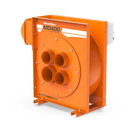
Specifications Specifications of MD400 and MD500 chip extractors SECTION 3 SPECIFICATIONS Specifications of MD400 and MD500 chip extractors Wood-Mizer chip extractors nomenclature is given in the table below. Chip Extractor Model MD400EA3U MD400EB3U MD500EB5U Motor Type Electric Motor Electric Motor... - Page 12 Specifications Specifications of MD400 and MD500 chip extractors MD500 Overview: TD-MD500-01 Output port 2x8" Outlet (310-501) 10" Outlet (537890-US) Input port 10" Inlet (537899-US) 5x4" + 1x5" Inlet (310-010-US) 3x4", 1x5" Inlet (537853-US) FIG. 3-2 When using a collection system, keep in mind: Check your local waste disposal codes before designing your chip collection sys- tem.
-
Page 13: Overall Dimensions
Specifications Overall dimensions Overall dimensions The overall dimensions of both MD400 and MD500 chip extractors and the bagging system are shown below (all dimensions in foot-inches). MD 400 Layout FIG. 3-3 MD500 Layout FIG. 3-4 Specifications WM doc 4/14/21... - Page 14 Specifications Overall dimensions Bag Collector Assembly Layout FIG. 3-5 WM doc 4/14/21 Specifications...
-
Page 15: Section 4 Setup
Setup Attaching the Chip Extractor SECTION 4 SETUP Attaching the Chip Extractor NOTICE Do not use your Chip Extractor if flexible hoses are not attached to it. All unused ports must be securely blocked off. Do not run your Chip Extractor with open ports. - Page 16 Setup Optional Cyclone Twin Bag Collector Assembly FIG. 4-2 2. Attach the hose adapter to the frame with 4 of the long screws with lock washers. Use the lower 4 holes. 3. Position the leg with the cutout on the corner by the hose adapter as shown below: FIG.
- Page 17 Setup Optional Cyclone Twin Bag Collector Assembly 6. Attach the remaining 3 legs with the short screws, flat washers and nuts. 7. Insert the rods into the bag bands as shown below: FIG. 4-5 8. Place the bag bands with rods into the bags as shown below: FIG.
- Page 18 Setup Optional Cyclone Twin Bag Collector Assembly 10. Place bag locks over the frame openings as shown below: FIG. 4-7 11. Place the bags over the frame openings by inserting the rods into the mounting holes as shown above: 12. Tuck the bag between the frame openings and the bag locks. 13.
- Page 19 Setup Optional Cyclone Twin Bag Collector Assembly 15. Swing the square trash bag bracket down by unclipping two latches holding the bracket. 16. Place the trash bag through the bracket as shown below: FIG. 4-9 NOTE: Ensure that the trash bag full covers the bracket or leakage may occur. 17.
-
Page 20: Section 5 Operation
Check your chip extractor as soon as you receive it. Report any transport damage to the transport company imme- diately. Spare parts should be sourced through Wood-Mizer. All electrical installation, service and/or maintenance should be performed by a qualified electrician. - Page 21 Operation Collection System Operation 1. Connect outlet hose to collection system inlet with hose clamps. 2. Turn on extraction system. 3. Monitor the fill rate of the collection bags. If one bag is filling faster than the other one, turn the flow adjustment knob to even the flow rate.
-
Page 22: Section 6 Troubleshooting Guide
Troubleshooting Guide General Troubleshooting SECTION 6 TROUBLESHOOTING GUIDE General Troubleshooting DANGER! Disconnect power before clearing debris or any other maintenance activity. Failure to follow this will result in serious injury or death. Follow the OSHA lockout procedures reprinted in the Safety section. Keep hands away from the knives. -
Page 23: Extractor Optimization
Troubleshooting Guide Extractor Optimization Problem Possible Cause Solution Motor has overheated Motor amperage too high and • System running with little to no resistance. Do not tripped overload protector run the extractor without inlet and outlet hosing. Seal all unused ports. •... - Page 24 Troubleshooting Guide Extractor Optimization WM doc 4/14/21 Troubleshooting Guide...
-
Page 25: Section 7 General Information
From the continental U.S., call 1-800-525-8100 to order parts. Have your customer number, serial number (VIN when applicable), and part numbers ready when you call. From international locations, contact the Wood-Mizer distributor in your area for parts. General Information... -
Page 26: Chip Extractor, 3Kw 230V Single Phase, 3Kw 230V Three-Phase
116001 4" Duct Hose 116000 Assy, Mounting Feet 537830-US Weldment, MD400 Frame 537835-US Assy, MD400 Motor/Fan Drive, 3kW, 1Ph (MD400EA3U) 123361 123260 Assy, MD400 Motor/Fan Drive, 3kW, 3Ph (MD400EB3U) Assy, Motor Starter, 1ph (MD400EA3U) 123392 123393 Assy, Motor Starter, 3ph (MD400EB3U) -
Page 27: Chip Extractor, 3Kw 230V Three-Phase
General Information Chip Extractor, 3kW 230v Three-Phase Chip Extractor, 3kW 230v Three-Phase MD500EB5U-SYS DESCRIPTION (♦ Indicates Parts Available in Assemblies Only) PART # QTY. CHIP EXTRACTOR, MD500 3PH COMPLETE SYS MD500EB5U-SYS 2 Bag Dust Collection System w/Filter 301-008-US Assy, 2x8" Outlet 310-501 Assy, 5x4"... -
Page 28: Motor/Fan Drive, 3Kw, Single-Phase
General Information Motor/Fan Drive, 3kW, Single-Phase Motor/Fan Drive, 3kW, Single-Phase 123361 DESCRIPTION (♦ Indicates Parts Available in Assemblies Only) PART # QTY. ASSY, MD400 MOTOR/FAN DRIVE, 3KW, 1PH 123361 Bolt, M10-1.5x25 SHC F05022-12 Washer, 10mm Split Lock F05011-88 Washer, .44IDx2.00ODx1/8... -
Page 29: Motor/Fan Drive, 3Kw, Three-Phase
General Information Motor/Fan Drive, 3kW, Three-Phase Motor/Fan Drive, 3kW, Three-Phase 123260 DESCRIPTION (♦ Indicates Parts Available in Assemblies Only) PART # QTY. ASSY, MD400 MOTOR/FAN DRIVE, 3KW, 3PH 123260 Washer, .35IDx2.00ODx1/8 123357 Gasket, Front Mount 537839-US Plate, Motor Mount, 90 Frame... -
Page 30: Motor/Fan Drive, 5.5Kw Three-Phase
General Information Motor/Fan Drive, 5.5kW Three-Phase Motor/Fan Drive, 5.5kW Three-Phase 123264 DESCRIPTION (♦ Indicates Parts Available in Assemblies Only) PART # QTY. ASSY, MD500 MOTOR/FAN DRIVE 123264 Bolt, M10-1.5x25 SHC F05022-12 Washer, 10mm Split Lock F05011-88 Washer, .44IDx2.00ODx1/8 123395 Gasket, Front Mount 537839-US Plate, Motor Mount, 100/112 Frame 537896-US... -
Page 31: Motor Starter
General Information Motor Starter Motor Starter 123393 DESCRIPTION (♦ Indicates Parts Available in Assemblies Only) PART # QTY. ASSY, MOTOR STARTER, 1PH (MD400EA3U) 123392 ASSY, MOTOR STARTER, 3PH (MD400EB3U) 123393 ASSY, MOTOR STARTER, 3PH(MD500EB5U) 123394 Screw, M5-.8x25mm SHBC F05020-38 Bolt, M8x1.25x20mm SHCS F05005-150 Washer, M8 Flat F05026-4... -
Page 32: 3X4", 1X5" Inlet
General Information 3x4", 1x5" Inlet 3x4", 1x5" Inlet 537853-US DESCRIPTION (♦ Indicates Parts Available in Assemblies Only) PART # QTY. ASSY, 3X4", 1X5" INLET 537853-US Clamp, Worm, 3 1/8 - 6 Dia 123356 Cap, 4" OD 123295 Cap, 5" OD 123296 Bolt, M8x1.25x20mm SHCS F05005-150... -
Page 33: 5X4" + 1X5" Inlet
General Information 5x4" + 1x5" Inlet 5x4" + 1x5" Inlet 310-010-US DESCRIPTION (♦ Indicates Parts Available in Assemblies Only) PART # QTY. ASSY, 5X4" + 1X5" INLET 310-010-US Weldment, 5x4", 1x5" Inlet 537927-US Gasket, Front Mount 537839-US Bolt, M8x1.25x20mm SHCS F05005-150 Washer, M8 Split Lock F05011-45... -
Page 34: 10" Inlet
General Information 10" Inlet 7.10 10" Inlet 537899-US DESCRIPTION (♦ Indicates Parts Available in Assemblies Only) PART # QTY. ASSY, 10" INLET 537899-US Gasket, Front Mount 537839-US Washer, M8 Split Lock F05011-45 Bolt, M8x1.25x20mm SHCS F05005-150 Clamp, Worm, 3 1/8 - 6 Dia 123356 Weldment, 10"... -
Page 35: 8" Outlet
General Information 8" Outlet 7.11 8" Outlet 5370870-US DESCRIPTION (♦ Indicates Parts Available in Assemblies Only) PART # QTY. ASSY, 8" OUTLET 537870-US Gasket, Small Outlet 537846-US Nut, M8 x 1.25 Flanged Nylock F05027-44 Washer, M8 Split Lock F05011-45 Bolt, M8x1.25x20mm SHCS F05005-150 Clamp, Worm, 7 1/8 - 10"... -
Page 36: 2X8" Outlet
General Information 2x8" Outlet 7.12 2x8" Outlet 310-501 DESCRIPTION (♦ Indicates Parts Available in Assemblies Only) PART # QTY. ASSY, 2X8" OUTLET 310-501 Bolt, M8x1.25x20mm SHCS F05005-150 Washer, M8 Split Lock F05011-45 Nut, M8 x 1.25 Flanged Nylock F05027-44 Gasket, Outlet, Large 537891-US Washer, M8 Flat F05026-4... -
Page 37: 10" Outlet
General Information 10" Outlet 7.13 10" Outlet 537890-US DESCRIPTION (♦ Indicates Parts Available in Assemblies Only) PART # QTY. ASSY, 10" OUTLET 537890-US Clamp, Worm, 3 1/8 - 6 Dia 123356 Weldment, 10" Outlet 537889-US Gasket, Outlet, Large 537891-US Bolt, M8x1.25x20mm SHCS F05005-150 Washer, M8 Split Lock F05011-45... -
Page 38: Mounting Feet
General Information Mounting Feet 7.14 Mounting Feet 537871-US DESCRIPTION (♦ Indicates Parts Available in Assemblies Only) PART # QTY. ASSY, MOUNTING FEET 537905-US ASSY, MOUNTING FEET 537830-US Bracket, Large Stand (537905-US only) 537871-US 537833-US Bracket, Small Stand (537830-US only) Washer, M8 Flat F05026-4 Bolt, M8x1.25x20mm SHCS F05005-150... -
Page 39: Bagging System
General Information Bagging System 7.15 Bagging System 301-008-US DESCRIPTION (♦ Indicates Parts Available in Assemblies Only) PART # QTY. 2 BAG DUST COLLECTION SYSTEM W/FILTER 301-008-US Bracket, Top Table 123297 Caster, Swivel, 2ODx2 5/8 Height 123298 Collection Bag (65 Gallon) 123318 General Information WM doc 4/14/21... - Page 40 General Information Bagging System DESCRIPTION (♦ Indicates Parts Available in Assemblies Only) PART # QTY. Assy, Bag Clamp 123365 Assy, 8" Outlet 537870-US Weldment, Bagging 537950-US Bracket, Leg 537972-US Bracket, Leg 537973-US Weldment, Flow Diverter 537974-US Knob, M8 537977-US Weldment, Filter Upright 537980-US Rod, Filter Stand 537981-US...
-
Page 41: Bag Clamp
General Information Bag Clamp 7.16 Bag Clamp 123365 DESCRIPTION (♦ Indicates Parts Available in Assemblies Only) PART # QTY. ASSY, BAG CLAMP 123365 Latch, Draw 123363 Flat, Foam 123366 Bracket, Latch Mount 537958-US Bracket, Bag Lock 537961-US Weldment, Bag Clamp 537969-US Bolt, #6-32x3/8 Socket BH F05004-65...
Need help?
Do you have a question about the MD500 and is the answer not in the manual?
Questions and answers