Table of Contents
Advertisement
Quick Links
INSTALLATION AND
OPERATION MANUAL
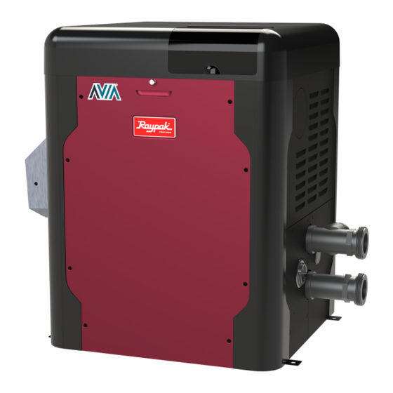
Gas-Fired Pool
and Spa Heater
Models 264 and 404
WARNING: If the information is not followed exactly, a fire or explosion may result causing property
damage, personal injury or death.
— Do not store or use gasoline or other flammable vapors and liquids or other combustible materials
in the vicinity of this or any other appliance. To do so may result in an explosion or fire.
— WHAT TO DO IF YOU SMELL GAS
• Do not try to light any appliance.
• Do not touch any electrical switch; do not use any phone in your building.
• Immediately call your gas supplier from a neighbor's phone. Follow the gas supplier's instructions.
• If you cannot reach your gas supplier, call the fire department.
— Installation and service must be performed by a qualified installer, service agency or the gas supplier.
This manual should be maintained in legible condition and kept adjacent to the heater or in a safe place for future
reference.
APPROVED
UNCONTROLLED DOCUMENT IF PRINTED
Effective: 08-20-21
Replaces: 241807 Rev. 5
P/N: 241807 Rev. 6
Advertisement
Table of Contents
Troubleshooting

Related Manuals for Avia 404

Summary of Contents for Avia 404
- Page 1 OPERATION MANUAL Gas-Fired Pool and Spa Heater Models 264 and 404 WARNING: If the information is not followed exactly, a fire or explosion may result causing property damage, personal injury or death. — Do not store or use gasoline or other flammable vapors and liquids or other combustible materials in the vicinity of this or any other appliance.
- Page 2 APPROVED QUICK START GUIDE CLEARANCES WATER CHEMISTRY † Space required: See pages 7-9. † Water chemistry requirements: See page 5. † Minimum and service clearances: See page 7 for clearances table. Note that local codes prevail. POWER † Supply voltage: See page 25 for acceptable input voltages.
-
Page 3: Table Of Contents
APPROVED TABLE OF CONTENTS 1. WARNINGS ............. 4 Program Menu ............31 Pay Attention to These Terms ......... 4 Control Lockout ............. 34 General Safety ............5 Status and Diagnostics ......... 34 Remote Wired Control Installation 2. WATER CHEMISTRY ..........5 and Operation .......... -
Page 4: Warnings
APPROVED 1. WARNINGS Pay Attention to These Terms Indicates the presence of immediate hazards which will cause severe personal injury, death or DANGER substantial property damage if ignored. Indicates the presence of hazards or unsafe practices which could cause severe personal injury, WARNING death or substantial property damage if ignored. -
Page 5: General Safety
APPROVED For your health and the protection of your pool equipment, General Safety it is essential that your water be chemically balanced. The Elevated water temperature can be hazardous. The following levels must be used as a guide for balanced U.S. -
Page 6: Before Installation
APPROVED 3. BEFORE INSTALLATION Rating and Certifications These heaters are design-certified and tested under the Receiving Equipment latest requirements of the ANSI Z21.56 / CSA 4.7 Standard The manufacturer recommends that this manual be for Gas-Fired Pool Heaters. This product is also certified reviewed thoroughly before installing the pool/spa heater. -
Page 7: Installation Codes
APPROVED Flooring WARNING: Improper installation, adjustment, alteration, service or maintenance may damage the This heater can be installed on combustible flooring. equipment, create a hazard resulting in asphyxiation, Outdoor Heater Installation explosion or fire, cause damage which will not be covered under warranty. - Page 8 APPROVED V = VENT X = AIR INLET F10692 Figure 3. Minimum Clearances from Vent/Air Inlet Terminations – Indoor and Outdoor Installations U.S. Installations Canadian Installations Clearance above grade, veranda, porch, deck, or 1' (30 cm) 1' (30 cm) balcony 4' (1.2 m) below or to side of Clearance to window or door that may be opened 3' (91 cm)
- Page 9 APPROVED For U.S. installations, the point from where the flue Distance Description Location products exit the heater must be a minimum of 4' (1.2 m) in. (mm) below, 4' (1.2 m) horizontally from, or 1' (0.3 m) above any Back 9 (229) Right 9 (229)
-
Page 10: Combustion And Ventilation Air
Sq. in. (m²) A. In the US, the total cross-sectional area shall be at least 1 in.² of free area per 20,000 BTUH (111 264 (0.17) mm² per kW) of total input rating of all equipment 399 (0.26) in the room when the opening is communicating directly with the outdoors or through vertical Table E. - Page 11 APPROVED Florida and Texas Building Code: Wind Speed = 180 mph 3-sec. gust Exposure = C 29" (73.6 cm) 30.38" (77.1 cm) 16.92" (43.0 cm) 3" (76 mm) Min. Conc. Min. Edge Pad by others Distance 6" (152 mm) Min. Edge Distance 6"...
- Page 12 APPROVED Specifications and Dimensions Amp Draw CONTROL DISPLAY 120 VAC, 1 Ph, 60 Hz 240 VAC, 1 Ph, 60 Hz AND INTERFACE 1.6A 1.2A OUTDOOR FLUE COVER 30.38” (772 MM) Water Inlet 14.63” Water Outlet 10.14” (372 MM) (258 MM) 5.61”...
-
Page 13: Venting
APPROVED Venting NOTE: For additional information on appliance CAUTION: Proper installation of flue venting is categorization, see the ANSI Z21.13 Standard and the critical for the safe and efficient operation of the pool NFGC (U.S.), or B149 (Canada), or applicable provisions heater. - Page 14 APPROVED Support of Vent Stack U.S. Installations The weight of the vent stack or chimney must not rest Refer to the latest edition of the National Fuel Gas Code. on the heater vent connection. Support must be provided Vent termination requirements are as follows: in compliance with applicable codes.
- Page 15 (mm) Material Min. Max. Category I (Type B 264/404 4 (101.6) 5 (1.5) 25 (7.6) Equivalent) Fan-Assisted Vent lengths are based on a lateral length of 2 ft (0.6 m). Refer to the latest edition of the NFGC for further details. When vertical height exceeds 25 ft (7.6 m), consult factory prior to installation.
- Page 16 (m) Pipe Material** Material ft (m) ft (m)* 4" Ø Galvanized Steel, PVC, 264/404 Category III 4 (1.2) 75 (22.86) 75 (22.86) ABS, CPVC * Subtract 12 ft (3.6 m) per elbow. ** Schedule 40 in PVC or CPVC.
- Page 17 APPROVED Care must be taken during assembly that all joints are Use only the special gas vent pipes listed for use with sealed properly and are airtight. Category III gas burning heaters, such as the AL29- 4C stainless steel vents offered by DuraVent (www. The vent must be installed to prevent the potential duravent.com).
-
Page 18: Gas Supply Connections
APPROVED Gas Supply Connections VERTICAL VENT 3’ MIN H E AT ER CAP TERMINATION (915 MM) GA S J A C K E T INTAKE VENT S U P P LY M A N U A L I N LE T S H U TOF F 3’... -
Page 19: Flow Rates
Pipe Size Model Min. GPM (lpm) Max. GPM (lpm) UNION in. (mm) 264/404 2 (50.8) 40 (151) 100 (379) * When flow rates exceed maximum GPM an external auxiliary bypass valve is required. See External Bypass Valve Section on page 21 for details. -
Page 20: Protek Shield Assembly
APPROVED High-temperature CPVC header flanges and header CAUTION: Do not use tools to remove (twist) the flange nuts are provided. If there is any possibility of back- ProTek Shield Assy or the wing nut on the stud of the siphoning when the pump stops, it is highly recommended ProTek Shield Assy. -
Page 21: Internal Automatic Bypass Valve
APPROVED Internal Automatic Bypass Valve Auxiliary Bypass Valve Adjustment To set bypass - With clean filter, adjustment is made by In addition to the Unitherm Governor, a built-in automatic bypass valve is provided in the In/Out header. While the feeling the inlet and outlet pipes at the heater. Outlet pipes Unitherm Governor responds to the changes in water should be slightly warmer than inlet and comfortable to the temperature in the heater, the internal bypass valve... - Page 22 APPROVED NOTE: To avoid water damage or scalding due to valve operation, drain pipe must be connected to the outlet of the PRV and run to a safe place of discharge. Drain pipe must be the same size as the valve discharge connection throughout its entire length and must pitch downward from the valve.
-
Page 23: Plumbing Diagram
APPROVED Plumbing Diagram Water Connection ISOLATION VALVE BALL VALVE THIS DIAGRAM IS A RECOMMENDATION AND IS NOT INTENDED PRESSURE RELIEF VALVE TO REPLACE AN ENGINEERED PIPING SYSTEM BY A PROFESSIONAL ENGINEER PUMP Figure 24. Single Pool Heater Installation UNION CHECK VALVE THIS DIAGRAM IS A RECOMMENDATION AND IS NOT INTENDED TO REPLACE AN ENGINEERED PIPING SYSTEM BY A PROFESSIONAL ENGINEER Figure 25. -
Page 24: Water/Flue Connection Reversal
APPROVED 5. ELECTRICAL WIRING Water/Flue Connection Reversal The heater is designed so that the control panel along with NOTE: If it is necessary to replace any of the original the top can rotate in 90-degree increments to face the user. wiring, use 150°C wire or its equivalent. -
Page 25: Transformer Wiring
APPROVED Transformer Wiring 120 VAC Wiring For 120 VAC input power to the unit, connect the field supplied Black wire (L1) to the (2) Black wires from the heater. Connect the white and red/white wires to the "N" or Neutral leg of the power supply. There should be no connection to the red wire for 120 VAC operation. -
Page 26: Wiring Diagram
APPROVED 6. WIRING DIAGRAM HIGH TENSION HIGH TENSION INLET TEMPERATURE INLET TEMPERATURE OUTLET TEMPERATURE OUTLET TEMPERATURE SENSOR SENSOR SENSOR SENSOR WATER PRESSURE / FLOW SWITCH IGNITOR IGNITOR HI TEMP LIMIT SWITCH #1 G BK G BK NO – Normally Open HI TEMP LIMIT SWITCH #2 NC –... -
Page 27: Controls
APPROVED 7. CONTROLS HEATER TOP CONTROL BEZEL SCREW HOLE SCREW HOLE INLET SENSOR PROTEK SHIELD OUTLET SENSOR ASSY Figure 34. Heater Top Removal UNITHERM PRESSURE SWITCH TEMP SENSOR GOVERNOR Control Adjustments HL1 - HIGH LIMIT F108390-1 HL2 - HIGH LIMIT The pool heater touchpad, located on the upper front Figure 32. -
Page 28: Operation
APPROVED Press the DOWN key. The "Hours" run time indicates the Operation total hours of operation for the pool heater, as measured by In the POOL or SPA modes, the actual water temperature the amount of time that the gas valve has been powered. is displayed along with the desired water temperature The "Cycles"... - Page 29 APPROVED Vent Temperature Pool Est 11500 gl Press the DOWN key. The Vent Temperature screen Heat Time 120 min indicates the temperature sensed in the vent. Vent Temperature Spa Est 1000 gl 285 F Heat Time 45 min Figure 42. Vent Temperature Figure 44.
- Page 30 APPROVED Available in some configurations SERVICE SERVICE and kits Flame Strength Flame Strength Flame Strength 9.5uA 9.5uA Supply Voltage Supply Voltage Supply Voltage Run Counters Hours Hours Power Power Cycles Cycles Faults History Last Err Last Err DOWN DOWN OFF mode Inlet Temp Fail Inlet Temp Fail Fault 1...
-
Page 31: Program Menu
APPROVED Program Menu Language Selection To access PROGRAM menu, press and hold SERVICE Initial display in PROGRAM Menus is "Language" and MODE keys simultaneously for 5 to 7 seconds until selection. "Language" appears on the display. The UP and DOWN keys will select English, Spanish or French language for all menus and Display messages. - Page 32 APPROVED Wi-Fi Reset Pump Control Press the SERVICE key until "Wi-Fi Reset" appears on the Press the SERVICE key until "Pump Control" appears digital display. Press and hold SERVICE and MODE keys on the digital display. The UP or DOWN keys will select simultaneously for 3 to 5 seconds until "Wi-Fi Initialized"...
- Page 33 APPROVED Operation Mode WiFi Reset Available in some Pool configurations and kits WiFi Reset WiFi Reset WiFi Initialized WiFi Initialized SERVICE SERVICE MODE MODE MODE MODE 5 sec PROGRAM Menu SERVICE SERVICE Automation Mode Language Automation Mode Automation Mode Language Language Enabled Enabled...
-
Page 34: Control Lockout
APPROVED Control Lockout Status and Diagnostics The heater is equipped with a Control Lockout feature The LCD displays a variety of status and diagnostic to prevent unauthorized tampering or adjustment of the messages, depending on the operating conditions. control settings. To lock out the controls, press the MODE The following heat status messages are displayed in Pool, and DOWN keys simultaneously for 5-seconds. - Page 35 APPROVED The following conditions are displayed in Pool, Spa and The following conditions are displayed only while there is a Remote modes when there are active fault conditions. demand for heat present. Display Condition Display Condition Flame Lost Flame was not detected. Water Inlet thermistor temperatures In Sensor Fault Water Sw Open...
-
Page 36: Remote Wired Control Installation And Operation
APPROVED WARNING The ability to properly perform service on Activating the Remote this equipment requires certain expertise, mechanical To activate or deactivate the remote function, press and skills, tools, and equipment. If you do not possess hold the UP and DOWN arrow keys for 3 to 5 seconds. these, do not attempt to perform any service on this equipment other than those procedures recommended The second line of the display will alternate even when the... - Page 37 APPROVED NOTE: The remote wires must be connected to the 3-pin connector before the connector is plugged into the board. 2-Wire Remote Control (On-Off) This application assumes that only one heating function COMMANDS REMOTE SPA (pool or spa) is required. WIRE NUT BK/ORN SWITCH 1.
-
Page 38: Time Clock/Fireman's Switch
APPROVED 1. Make sure the pool filter is clean before adjusting Time Clock/Fireman’s Switch the switch. To operate the heater with a time clock, connect the timer 2. Set the heater control to the OFF mode. to the clock/fireman’s switch connection in the heater’s 3. - Page 39 APPROVED High Limits MAY REQUIRE ADJUSTMENT The heater is equipped with two high limits, both are FOR LOWER PRESSURE automatic and are located in the inlet/outlet header. Although both limits are preset to auto-reset, the control board will request the operator to press "mode" if either limit is tripped while the heater is running.
- Page 40 APPROVED Orifice Removal Pockets / Model Gas Type Finish Notches 1. Locate and close the external manual shutoff valve. Natural None 2. Loosen the external gas union. 3. Locate and remove jacket top. Propane Black 4. Locate and remove the four (4) bolts & nuts holding the gas orifice in place.
- Page 41 APPROVED 2. Remove top cover. Disconnect power leads from rocker switch along with the cable attached to the user interface. Then set cover aside. (*It will be easier GAS VALVE to work on heater with the cover totally removed but might not be necessary*).
- Page 42 APPROVED 1. Follow the heat exchanger removal process as gasket with a non-petroleum based grease such as shown in "Heat Exchanger Removal" section. AquaLube. UG PLUG 2. The heat exchanger has a baffle on the sides, or the UG PLUG O-RING bottom, depending on the model size, which has to be removed.
-
Page 43: Operating Instructions
APPROVED 8. OPERATING WARNING: Should overheating occur or the gas supply fail to shut off, turn off the manual gas control to INSTRUCTIONS the appliance. Before Start-Up Water Pressure Switch A water pressure switch is provided in the heater to shut off Burners the burners in the event that water supply is interrupted. - Page 44 APPROVED OPERATING INSTRUCTIONS AND SHUTOFF PROCEDURES FOR YOUR SAFETY READ BEFORE LIGHTING A. This appliance does not have a pilot. It is equipped C. Use only your hand to turn the gas control ON or OFF. with an ignition device which automatically lights Never use tools.
-
Page 45: Maintenance And Care
APPROVED COLD CLIMATE: Prolonged operation with water 9. MAINTENANCE AND CARE temperatures below 50°F (10°C) is not recommended. When starting the heater with water temperatures below WARNING: Check the heater for possible rodent 50°F (10°C), operate the heater continuously until higher nests after long periods of non-use. -
Page 46: Troubleshooting
10. TROUBLESHOOTING APPROVED IMPORTANT NOTICE: These instructions are intended for the use of qualified personnel who are specifically trained and experienced in the installation of this type of heating equipment and related system components. Installation and service personnel may be required by some states to be licensed. Persons not qualified shall not attempt to install this equipment nor attempt repairs according to these instructions. -
Page 47: Operation And Troubleshooting - Flow Chart
APPROVED Operation and Troubleshooting - Flow Chart Operation and Troubleshooting – Flow Chart WARNING: HIGH VOLTAGE WARNING: HIGH VOLTAGE For qualified technicians ONLY For qualified technicians ONLY START NOTE: Before troubleshooting, familiarize yourself with the start-up and Turn Gas Supply OFF. check-out procedure Adjust Temperature Setpoint to Call for Heat... -
Page 48: Control Logic - Flow Chart
APPROVED Control Logic - Flow Chart Temperature-Resistance (kΩ) Control Logic – Flow Chart Below Above Fahrenheit Celcius Inlet Sensor fault fault Outlet Sensor fault fault START Below Temperature-Resistance (kΩ) Above Fahrenheit < 7.5 Celcius < -13 Power On Flue Sensor fault fault 1.03... -
Page 49: Connect To Wi-Fi With Raymote
See Figure 81. Figure 78. Log in the Raymote Mobile App Preparing the Unit for Connection Figure 75. Welcome Raypak Dashboard 1. Stand near the display of the AVIA unit. Press the CONNECT key. See Figure 79. Water Temp Water Temp Figure 79. -
Page 50: Add A New Device On Your Android
83. Figure 81. Add New Device 1. "Check your Device" screen will appear. Ensure to have AVIA heater powered and Wi-Fi signal available in the area, then press "Ready" button. See Figure Figure 83. Link with Raymote... - Page 51 APPROVED 3. You may be prompt to confirm selected heater. Wait a NOTE: The first time you use a new phone, the Raymote few seconds while the Raymote app connects to your mobile app will require you grant permission to access heater as shown in Figure 84.
-
Page 52: Add A New Device On Your Iphone
See Figure 91. Add a New Device on your IPhone 1. "Check your Device" screen will appear. Ensure to have AVIA heater powered and Wi-Fi signal available in the area, then press the "Ready" button. Figure 91. Grant Permission 4. -
Page 53: For Iphone 6 And Earlier Versions
Figure 94. Wi-Fi Setup network credentials to your unit. See Figure 93. 3. "Check your Device" screen will appear. Ensure to have AVIA heater powered and Wi-Fi signal available in the area, then press the "Ready" button. Figure 93. Configuring Device For iPhone 6 and Earlier Versions Figure 95. - Page 54 APPROVED 5. On the top left corner of the screen, press the NOTE: The first time you use a new phone, the Raymote "Settings" button to go the Settings menu. See mobile app will require you grant permission to access Figure 98.
-
Page 55: Configure Your Device
APPROVED 9. The Raymote mobile app will provide the Wi-Fi network credentials to your unit. See Figure 102. Figure 100. Select the HOTSPOT Identifier 8. A notification tab will confirm that iPhone is now connected to the unit. Press the notification tab or Figure 102. - Page 56 APPROVED 2. Press the "Set up as new" button to enter new identification and service information. Press the "Apply recently used profile" button to use information already provided. See Figure 104. Figure 104. Device Setup as New 3. During device configuration, basic reference Figure 105.
-
Page 57: Raymote Mobile App
APPROVED 12. RAYMOTE MOBILE APP Raymote Mobile App Navigation 1. Open Raymote and Sign up or Log in. See Figure 106. 2. Once Raymote App is opened, click on top left icon. See Figure 107. 3. Main menu will appear to choose from options to view. -
Page 58: Automation
APPROVED At the bottom of the welcome screen is the notification access point. By pressing this icon, users can access a summary of alerts and events for a given time frame, for all the registered units. See Figure 110. Figure 110. Notification Screen Alerts, events and diagnostic notifications are listed, with different colors for easy identification. -
Page 59: Accessories Screen
APPROVED Accessories Screen The accessories screen includes the auxiliary and extended heater controls in the Raymote mobile app. These controls allow users to command an Auxiliary relay that can be wired to turn on and off a pump, lights or water features. When unit is equipped with Water Chemistry board, up to 3 auxiliary outputs can be controlled. -
Page 60: Reset Wi-Fi Credentials
APPROVED Reset Wi-Fi Credentials Reconnect to Wi-Fi Resetting the Wi-Fi is useful when the heater is trying to Follow the next steps to reconnect a Heater already connect to a Wi-Fi signal that is not available or has been registered in Raymote, to a new Wi-Fi network or after a changed. - Page 61 APPROVED Figure 123. Confirm Selection 4. Now, standing near the heater, confirm device readiness and proceed with Wi-Fi configuration. Figure 121. Open Actions Menu 3. In “Actions” menu, select the option “Reconfigure”. Figure 124. Start Selection 5. Wait a few seconds while heater identifier is detected. 6.
- Page 62 APPROVED Figure 126. Set Wi-Fi Network and Password Figure 128. Exit to App 8. After this, Raymote will send the Wi-Fi configuration to the Heater. Figure 127. Configuring Device UNCONTROLLED DOCUMENT IF PRINTED...
-
Page 63: Auxiliary Control Output
13. AUXILIARY CONTROL route Auxiliary harness inside the cabinet to the controller OUTPUT board. See Figure 131. The AVIA heater offers an integrated dry contact relay for local and remote control of ON/OFF devices like Pumps, Water features, valves and lights. ROUTE... -
Page 64: Replacement Parts
APPROVED 14. REPLACEMENT PARTS NOTE: To supply you with the correct part, it is important that you supply the heater model number, serial number and type of gas when applicable. Any part returned for replacement under standard company warranties must be properly tagged with a return parts tag, completely filled in with the heater serial number, model number, etc., and shipped to the Company freight prepaid. -
Page 65: Illustrated Parts List
APPROVED 15. ILLUSTRATED PARTS LIST 18-S 18-S 10-S 13-S 11-S 12-S 16-S 15-S 14-S 17-S UNCONTROLLED DOCUMENT IF PRINTED... - Page 66 APPROVED UNCONTROLLED DOCUMENT IF PRINTED...
- Page 67 APPROVED 4-M 5-M 10-M UNCONTROLLED DOCUMENT IF PRINTED...
- Page 68 APPROVED UNCONTROLLED DOCUMENT IF PRINTED...
- Page 69 APPROVED 11-M (OPTIONAL) UNCONTROLLED DOCUMENT IF PRINTED...
- Page 70 APPROVED 12-M 12-H 13-H 10-H 10-C 11-H 16-H 15-H 14-H UNCONTROLLED DOCUMENT IF PRINTED...
- Page 71 APPROVED CALL DESCRIPTION 264A 404A BURNER Kit-Burner 018873F 018873F Kit-Burner Gasket 018878F 018878F CONTROLS Kit-Temp Sensor Limit 018853F 018853F Kit-Ignition Board 018857F 018933F Kit-Transformer 120/240/24V 018858F 018858F Kit-Pressure Vent 018928F 018928F Kit-Pressure Air 018929F 018929F Kit-Pressure Differential 018930F 018931F Kit-Temperature Inlet Sensor 019042F 019042F Kit-Temperature Outlet Sensor...
- Page 72 APPROVED MISCELLANEOUS COMPONENTS Kit-Top Cover Assy 018852F 018852F Kit-Top Lid 018902F 018902F Kit-Power Switch 018903F 018903F Kit-Bezel 018904F 018904F Kit-Top Clip Assy 018905F 018905F Kit-Top Knurled Screw Assy 018906F 018906F 10-M Kit-Bezel Gasket 018921F 018921F Kit-Power Cable Grommet 018884F 018884F Kit-Corner Post 018891F 018891F...
- Page 73 APPROVED CALL DESCRIPTION 264A 404A PILOT Kit-Igniter Direct Spark 018874F 018874F Kit-Igniter Gasket 018879F 018879F Kit-Hi Tension Wire 018875F 018875F REFRACTORY Kit-Refractory Assy 018848F 018848F SHEET METAL / CABINET Kit-Top Right Panel Assy Raypak/Rheem/Ruud (Cool Dark Gray) 018851F 018851F Jacuzzi (Beige) 018973F 018973F Kit-Cabinet Top Support...
-
Page 74: Important Instructions For The Commonwealth Of Massachusetts
APPROVED 16. IMPORTANT INSTRUCTIONS FOR THE COMMONWEALTH OF MASSACHUSETTS 2. Product Approved side wall horizontally vented gas fueled The Commonwealth of Massachusetts requires compliance with equipment installed in a room or structure separate from regulation 248 CMR 4.00 and 5.00 for installation of through – the the dwelling, building or structure used in whole or in part for –... -
Page 75: Warranty
APPROVED 17. WARRANTY LIMITED WARRANTY AVIA POOL AND SPA HEATERS Models: 264A, 404A SCOPE OF WARRANTY Raypak, Inc. (Raypak) warrants to the original owner that the above model gas pool and spa heater (the “Heater”) when installed in the contiguous 48 states of the United States of America with a pool or spa by a properly licensed installer will be free from defects in materials and workmanship under normal use and service for the Applicable Warranty Period. - Page 76 APPROVED extended warranty. Failure to register your product will not diminish your warranty rights. Please keep your proof of purchase. If you choose to register your purchase with Raypak, you may do as at www.raypak.com/warranty. CALIFORNIA EXTENDED WARRANTY PERIOD – BUILDER, NEW CONSTRUCTION For HEATERS sold in the state of California, if, within 90 days of the Effective Date, the HEATER is installed in a pool or spa at a single family residential dwelling by a properly licensed installer (in accordance with applicable state and local laws and regulations) then the Applicable Warranty Period is three (3) years parts and labor, from...
- Page 77 APPROVED purchase and/or installation and a description of the problem. Proper authorization MUST be obtained PRIOR to any repairs for the Limited Warranty to apply. This Limited Warranty is VOID if the Heater is repaired or altered in any way by ANY persons or agencies other than those authorized by Raypak.
- Page 78 APPROVED Notes Thank you for purchasing your Raypak AVIA pool heater from E-Z Test Pool Supplies, a leader in pool products, supplies, and service! Please keep this document for future reference and visit your account at eztestpools.com to obtain an invoice for registration purposes. If you need any additional assistance with your order, please call (603) 382-7010 to talk to E-Z Test Pool Supplies' knowledgeable staff or email order.support@eztestpools.com.
Need help?
Do you have a question about the 404 and is the answer not in the manual?
Questions and answers