
Related Manuals for Gullberg & Jansson P12


Summarization of Contents
1 General information
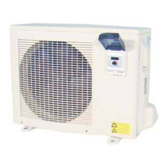
Product description
Details the models P08-P30 and their key features like titanium heat exchangers.
Functional principle
Explains the working principle, energy efficiency, and installation considerations.
Component part and accessories
Lists the main unit and installation accessories included with the heat pump.
Important information
Highlights key points on transport, storage, installation, usage, maintenance, and fault tracing.
Transport and storage
Provides guidelines for transporting and storing the heat pump to prevent damage.
Installation
Details requirements for outdoor installation on a firm, level surface, considering noise.
Use and operation
Explains that parameters are factory-set and provides guidance on operation.
Maintenance procedures
Outlines essential maintenance like winter drainage and regular checks for blockages.
Service and support
Advises contacting the installer for faults and provides information on locating the serial number.
Miscellaneous
States repair must be done by qualified engineers and discusses combining with solar collectors.
Checklist installation
Provides a checklist for ensuring proper installation steps are followed before startup.
Guarantee conditions
Outlines conditions for the guarantee to remain valid, covering transport, storage, and repairs.
Safety Regulations
Lists crucial safety instructions for handling, installation, and usage, including power disconnection.
2 Installation
Outline diagram
Shows a schematic diagram of the heat pump connected to the pool system.
Positioning the unit
Advises on ideal placement for access to fresh air and minimizing noise disturbance.
Set up
Details requirements for a firm, level base and proper drainage for condensation water.
Distance to the pool
Explains the effect of pipe length on heat loss and its impact on running time.
Leading off condensation water
Discusses condensation formation and the need for proper drainage of melt and condensation water.
Pipe connections
Describes connecting the heat pump to the pool circulation system using union couplings.
Bypass coupling
Recommends fitting a bypass coupling to regulate flow and protect the heat exchanger.
Adjusting the bypass
Provides a step-by-step guide on how to correctly adjust the bypass for optimal temperature difference.
Parallel coupling of several units
Explains how to connect multiple units in parallel for energy saving and balanced heating.
Electrical installation
Details electrical connection requirements, including the junction box, switch, and earthing.
Starting up the unit
Provides a step-by-step guide for the initial startup of the heat pump and circulation system.
3 Use and operation
Description of LED controls
Explains the LED display and how to check unit status and parameters.
How to change operating parameters
Details the procedure for shutting down the unit and changing various operating parameters.
How you select the operating mode
Explains how to switch between heating and cooling modes using the control knob.
Checking sensor values
Shows how to view various sensor values like inlet/outlet temperature and ambient temperature.
4 Maintenance, service and fault tracing
Winter drainage
Emphasizes the importance of winter draining to prevent damage to the heat exchanger.
Maintenance
Covers regular checks of water supply, filter cleaning, and area ventilation.
Fault tracing
Advises contacting the installer for faults and refers to the fault tracing guide.
Error code table
Lists error messages, their causes, and recommended actions for troubleshooting.
Fault charting table
Provides a table outlining causes and actions for common operating disturbances like temperature not reached or icing.
5 Technical specification
Connection key
Details the function of each terminal on the PC1001 connection board.
Wiring diagram
Presents a one-phase wiring diagram showing component connections and labels.
Technical data
Lists detailed technical specifications for each model, including output, power, and dimensions.
Dimensions and connections
Provides diagrams showing the physical dimensions and connection points for various models.
Need help?
Do you have a question about the P12 and is the answer not in the manual?
Questions and answers