Table of Contents
Advertisement
Quick Links
Advertisement
Table of Contents

Related Manuals for inDESIGN iDR-222

Summary of Contents for inDESIGN iDR-222
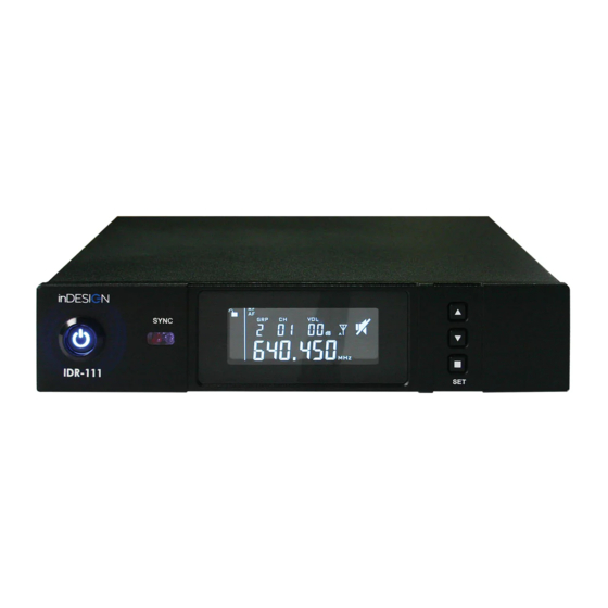
- Page 1 SYNC iDR-111 SYNC iDR-222...
-
Page 2: Table Of Contents
ELECTRICAL SHOCK, DO NOT EXPOSE THIS accompanying the appliance. APPLIANCE TO RAIN OR MOISTURE. magnitude to constitute a risk of electric shock to persons. PAGE 2 iDR-111 / iDR-222 / iDT-HM1 / iDT-BP1: INSTALLATION & OPERATION MANUAL... -
Page 3: Important Safety Instructions
They can take this product for environmental-safe recycling. WARNING: There are no user serviceable parts inside. Refer all servicing to qualified service personnel. iDR-111 / iDR-222 / iDT-HM1 / iDT-BP1: INSTALLATION & OPERATION MANUAL PAGE 3... - Page 4 LCD Display Screen. 4. Volume (+) button/menu function button. 5. Volume (-) button/menu function button. 6. SET button – Channel infrared data transmission (SYNC) button/menu settings button. PAGE 4 iDR-111 / iDR-222 / iDT-HM1 / iDT-BP1: INSTALLATION & OPERATION MANUAL...
- Page 5 9. Channel A/B 6.35 jack unbalanced output. 10. Mix/Separate output switch (iDT-222 only). 11. Mic/Line switch (Determines available output gain for either microphone or line outputs). 12. Power input (12Vdc 1.5A). iDR-111 / iDR-222 / iDT-HM1 / iDT-BP1: INSTALLATION & OPERATION MANUAL PAGE 5...
-
Page 6: Rackmount Diagram
Figure 1: Single Receiver Figure 2: Dual Receivers The iDR-111 & iDT-222 both ship with a rackmount kit. Each rackmount kit is capable of rack mounting either a single iDR-111/iDR-222 or a pair of iDR-111/iDR-222 receivers. PAGE 6 iDR-111 / iDR-222 / iDT-HM1 / iDT-BP1: INSTALLATION & OPERATION MANUAL... -
Page 7: Idr-111/Idr-222 Connections
Output mode switch (10) allows users to mix the outputs of both receiver channels to OUTPUT B 6.35mm TS Phono socket. The balanced XLR microphone outputs will continue to output their discrete receiver channel. iDR-111 / iDR-222 / iDT-HM1 / iDT-BP1: INSTALLATION & OPERATION MANUAL PAGE 7... -
Page 8: Antenna Extension
ANTENNA EXTENSION Both the iDR-111 and iDR-222 receivers are compatible with external powered and passive antenna extension products. Antenna A&B ports are designed to power inline antenna boosters and active antenna amplifiers. Each Antenna port provides 8-12v, 300ma DC power. -
Page 9: Lcd Display Layout & Menu Operation
Pressing the SET button once while in menu functions mode will scroll into the next menu function as illustrated below. HOME AUTO SCAN GROUP/CHANNEL SELECTION LOCK EQUALISER SQUELCH iDR-111 / iDR-222 / iDT-HM1 / iDT-BP1: INSTALLATION & OPERATION MANUAL PAGE 9... -
Page 10: Idr-111/Idr-222
“U” Group allows users to choose a specified frequency rather than a predetermined Group and Channel frequency allocation. Refer to pages 19-20 for the frequency tables. Note this feature is recommended only for advanced users. PAGE 10 iDR-111 / iDR-222 / iDT-HM1 / iDT-BP1: INSTALLATION & OPERATION MANUAL... - Page 11 The LCD display will show LOC OFF. Press the SET button 2 times to confirm the setting and exit the functions menu. iDR-111 / iDR-222 / iDT-HM1 / iDT-BP1: INSTALLATION & OPERATION MANUAL PAGE 11...
-
Page 12: Receiver & Transmitter Pairing
The MIC/LINE switch located on the rear panel allows users to choose the output signal gain structure. MIC output allows max Volume output of +6dB. LINE output allows max Volume output of +18dB. PAGE 12 iDR-111 / iDR-222 / iDT-HM1 / iDT-BP1: INSTALLATION & OPERATION MANUAL... - Page 13 9. Power button. Hold 2 seconds to power on/off. 10. MUTE button – Press button to mute audio transmission to receiver. When muted the button will light up. The LCD will also show “MUTE” status. iDR-111 / iDR-222 / iDT-HM1 / iDT-BP1: INSTALLATION & OPERATION MANUAL PAGE 13...
-
Page 14: Idt-Mh1 Lcd Display
1. Lock ON/OFF indicator. 2. RF transmission signal High/Low indicator (Low 3mW High 10mW). 3. Microphone capsule sensitivity (-6 dB to +6 dB). 4. Battery indicator. 5. Frequency display. PAGE 14 iDR-111 / iDR-222 / iDT-HM1 / iDT-BP1: INSTALLATION & OPERATION MANUAL... - Page 15 To unlock the transmitter, press the SET then DOWN Button and the unlock symbol will appear. Press the SET button again to confirm and exit the functions menu. iDR-111 / iDR-222 / iDT-HM1 / iDT-BP1: INSTALLATION & OPERATION MANUAL PAGE 15...
-
Page 16: Idt-Bp1 Controls
8. Battery compartment (use 2 x AA Alkaline). 9. RF transmit power (Low 3mW/High 10mW). 10. Infrared (IR) synchronisation window. Align this window with wireless transmitter IR sync window for radio frequency synchronisation. PAGE 16 iDR-111 / iDR-222 / iDT-HM1 / iDT-BP1: INSTALLATION & OPERATION MANUAL... -
Page 17: Idt-Bp1 Lcd Display
LCD display will show the frequency group and Group channel (eg. 2-012). 2. Battery level indicator – When battery level is low the battery low LED on the top panel of the belt pack will light up. iDR-111 / iDR-222 / iDT-HM1 / iDT-BP1: INSTALLATION & OPERATION MANUAL PAGE 17... -
Page 18: Specifications
8 hours High RF mode, 10 Hours Low RF mode Input Connection TA4 (M) Display Included Lapel Microphone Black electret condenser, Omni polar pattern * Disclaimer: Instructions and specifications are correct at time of printing. Information within may be subject to change without notice. PAGE 18 iDR-111 / iDR-222 / iDT-HM1 / iDT-BP1: INSTALLATION & OPERATION MANUAL... - Page 19 563.550 563.625 563.700 566.025 566.100 566.175 566.250 571.375 571.450 571.525 571.600 574.125 574.200 574.275 574.350 576.225 576.300 576.375 576.450 577.075 577.150 577.225 577.300 578.700 578.775 578.850 578.925 iDR-111 / iDR-222 / iDT-HM1 / iDT-BP1: INSTALLATION & OPERATION MANUAL PAGE 19...
- Page 20 673.550 673.625 673.700 676.025 676.100 676.175 676.250 681.375 681.450 681.525 681.600 684.125 684.200 684.275 684.350 686.225 686.300 686.375 686.450 687.075 687.150 687.225 687.300 688.700 688.775 688.850 688.925 PAGE 20 iDR-111 / iDR-222 / iDT-HM1 / iDT-BP1: INSTALLATION & OPERATION MANUAL...
- Page 21 NOTES iDR-111 / iDR-222 / iDT-HM1 / iDT-BP1: INSTALLATION & OPERATION MANUAL PAGE 21...
- Page 22 NOTES PAGE 22 iDR-111 / iDR-222 / iDT-HM1 / iDT-BP1: INSTALLATION & OPERATION MANUAL...
- Page 23 NOTES iDR-111 / iDR-222 / iDT-HM1 / iDT-BP1: INSTALLATION & OPERATION MANUAL PAGE 23...
- Page 24 The Warranty excludes accessories and consumable goods which have ceased working through normal wear and tear such as, but not limited to, batteries, lamps and other parts classifiable as a consumable part. This includes the CD mechanism and laser fitted to the inDESIGN iDCDP-110. These parts carry a 3 month warranty.
Need help?
Do you have a question about the iDR-222 and is the answer not in the manual?
Questions and answers