Table of Contents
Advertisement
Quick Links
Advertisement
Table of Contents

Related Manuals for Ebasto eThermo Top Eco 30 P

Summarization of Contents
1 Introduction
1.1 About this document
Details the purpose and audience of the workshop manual.
1.2 Purpose of the document
Explains that the manual contains information for resolving malfunctions of the eThermo Top Eco 20 P | 30 P.
1.3 Using this document
Instructs users to read and observe the manual, installation, and operating instructions.
1.4 Use of symbols and highlighting
Defines signal words (DANGER, WARNING, CAUTION, NOTE) and symbols used in the document.
1.5 Warranty and liability
Excludes liability for defects due to disregarded instructions or improper installation/use.
1.6 Qualifications of installation personnel
Specifies that only trained and qualified personnel should perform installation and repairs.
1.7 Spare parts
States that the unit must be replaced, but components like the coolant pump are available.
1.8 Safety precautions
Outlines critical safety warnings regarding electric shock, fire, and hot/moving objects.
1.9 Statutory regulations governing installation
Highlights compliance with directives and country-specific regulations for installation.
2 Information about the unit and external components
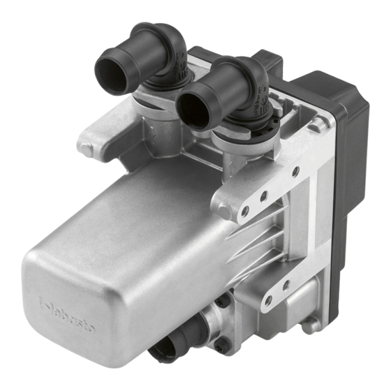
2.1 Overview
Provides a visual overview and list of the heater and its external components with reference numbers.
2.2 Heater - general information
Describes the eThermo Top Eco 20 P | 30 P as an electric water heater for preheating cabs and engines.
2.3 12 V wiring harness
Details the 12 V connections for the coolant pump, vehicle fan, and vehicle battery.
2.4 230 V heater supply cable / extension cable
Explains the 230 V power connection via a special cable with earth connection.
2.5 External components
Describes key external parts like the coolant pump, power cable, and fan relay.
4 Technical data
4.1 Dimensions
Presents the physical dimensions of the eThermo Top Eco 20 P | 30 P heater.
5 Malfunctions and troubleshooting
5.1 Cause of malfunctions
Lists potential causes of heater malfunctions including voltage issues, short circuits, and overheating.
5.2 Table of causes of fault
Provides a detailed table correlating symptoms with possible causes and corrective measures.
6 Function checks
6.1 General information
Describes checks for the heater and components in installed and uninstalled states.
6.2 Heater supply cable / extension cable
Details checks for the earth connection and security of the installation and extension cables.
6.3 Function check in the vehicle
Outlines steps for checking the vehicle fan, fresh air inlet, coolant circuit, and heating action.
6.4 Activation of vehicle blower
Covers checks for vehicle fan wiring, fuse, relay, and switch signals, including fan relay specifics.
6.5 Checking coolant pump
Specifies checks for coolant temperature, pump operation, and its cable connection/installation.
7 Servicing
7.1 Servicing
Describes servicing jobs to maintain functional reliability, recommended before/after each heating period.
7.2 Working on the heater
Provides critical safety instructions before working on the heater, including disconnecting power.
7.3 Maintenance
Details annual maintenance tasks, including checking coolant systems, connectors, and cables for damage.
8 Replacing the unit
8.1 General information
States that faulty heaters must be replaced, not repaired.
8.2 Required tools
Lists the specific tools needed for the removal and installation of the unit.
8.3 Removal
Details preliminary work, pinching hoses, releasing clips, and detaching connectors for unit removal.
8.4 Installation
States that installation is performed in the reverse order of removal, with specific instructions provided.
9 Packaging/storage and shipping
9.1 General information
Emphasizes maintaining specified ambient temperatures and protecting components during transit.
9.2 Storage and transportation
Provides recommendations for sending units, packaging, storage conditions, and transportation methods.
10 Wiring Diagram
10.1 Legend to wiring diagram
Explains the symbols and components used in the wiring diagram.
10.2 Legend for comments
Provides explanations for numbered comments or references within the wiring diagram.
10.3 Pin assignments plug connection X1, 2-pin
Details the pin configuration for the 2-pin plug connection X1.
10.4 Pin assignments plug connection X2, 2-pin
Details the pin configuration for the 2-pin plug connection X2.
10.5 Pin assignments plug connection X9, 3-pin
Details the pin configuration for the 3-pin plug connection X9.
10.6 Cable colours
Lists cable abbreviations and their corresponding colours used in the wiring diagram.
Need help?
Do you have a question about the eThermo Top Eco 30 P and is the answer not in the manual?
Questions and answers