Table of Contents
Advertisement
Quick Links
Advertisement
Table of Contents

Related Manuals for JEWELL IRIS

Summarization of Contents
Critical Operational Warnings
DC Current and Ohmmeter Usage Prohibition
Prohibits DC current and ohmmeter use to prevent permanent damage not covered by warranty.
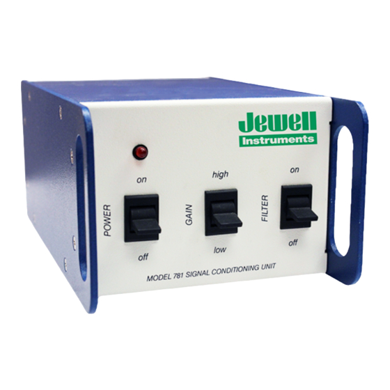
Signal Conditioning Unit Recommendations
Jewell Instruments Signal Conditioners
Lists and describes various Jewell signal conditioning units for tilt sensors.
Important Safety Warning
Prohibition of DC Current and Ohmmeter Testing
Reiterates the warning against using DC current or ohmmeters to test transducers, to prevent damage.
Troubleshooting Guide
Wiring Issues
Identifies faulty wiring or connections as a common cause of sensor problems.
Broken Transducer Symptoms
Describes symptoms like no/small output change, discoloration, or faint smell indicating a broken transducer.
Transducer Damage by DC Current
Explains permanent damage from DC current, plating of electrolyte, and reiterates prohibition.
Appendix A: Warranty and Assistance
Warranty Terms and Conditions
Outlines the one-year warranty, conditions for voiding, and repair policies.
Limitation of Liability
Specifies that JEWELL IS NOT LIABLE FOR INDIRECT, SPECIAL, OR CONSEQUENTIAL DAMAGES.
Appendix B: Custom Specifications
Customization Data Fields
Provides fields for recording serial, model, and axis details for specific tilt sensors.
Transducer Wire Color Coding
Wire Assignments for Tilt and Temp Sensors
Maps wire colors to functions for tilt transducers (+, E) and LM35 temperature sensors (T1, T2, T3).
Appendix B: Equipment Specifications
Signal Conditioning Unit Identification
Field to record the serial number of the Signal Conditioning Unit (SCU).
SCU Filter Settings and Scale Factors
Filter Time Constants and Cutoff Frequency
Details SCU filter settings, time constants (τ), and cutoff frequency (fc) calculations.
SCU Calibration for Tilt Transducers
Explains that the SCU is calibrated for specific tilt transducers and requires recalibration for new ones.
LM35 Precision Centigrade Temperature Sensors
LM35 Sensor General Description and Features
Provides details on the LM35's linearity, accuracy, temperature range, and key operational features.
LM35 Connection Diagrams and Applications
Illustrates connection diagrams for LM35 packages and typical application circuits.
Appendix C: Revision Table
Revision History and Changes
Documents revisions (D, E, F, G) with page numbers, ECN numbers, descriptions, and dates of changes.
Need help?
Do you have a question about the IRIS and is the answer not in the manual?
Questions and answers