Advertisement
INSTALLATION & OPERATING INSTRUCTIONS
( Model: TR2003, TR2004 ; Transmitter: T1003, T1004 + Receiver: RR12)
IF YOU CAN NOT READ OR UNDERSTAND THESE INSTALLATION INSTRUCTIONS, DO NOT ATTEMPT TO INSTALL OR OPERATE.
INTRODUCTION
This Durablow remote control system is to provide a safe and reliable control for gas heating appliances, such as fire
fireplace. The system can be operated thermostatically or manually from the transmitter (remote handset). The system
operates on radio frequencies (RF) within a 20-foot range and non-directional signals. The remote receiver box code
must be matched to the transmitter prior to initial use (see
Read ALL sections and original manufacturer manual for safety installation before any action. These safety features shut
down the system and appliance, such as fireplace when a potentially unsafe condition exists, such as high-heat.
PACKING LIST:
Please check and make sure all parts are in good condition before installation. Any questions, please do NOT return to
dealer, but email us
(info@payandpack.com)
shortly. Thank you.
1. Remote transmitter T1003 or T1004 (1),
2. Remote control receiver box RR12 with two signal wires (1),
3. USB power cord + adapter (1),
4. Wall mount cover plate (1),
5. Installation Instructions (1)
Fig. 1
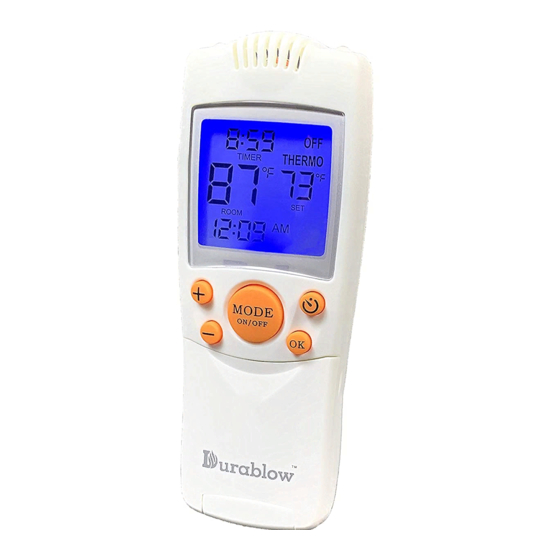
Transmitter Handset
LEARNING TRANSMITTER TO
and contact us on
Switch box
screw (2), Slide switch button (1)
Fig. 2
LCD display on transmitter
PayandPack.com
immediately, we will provide solutions
RECEIVER).
Version 20190806 Page
1
Advertisement
Table of Contents

Related Manuals for Durablow TR2004


Summarization of Contents
Installation and Operating Instructions
Introduction to the System
Overview of the Durablow remote control system for safe and reliable gas heating control.
Package Contents
Details all components included in the package for system setup and installation.
LCD Display Icons Explained
Low Battery Indicator
Alerts user to low battery power on the transmitter, requiring replacement within two weeks.
Timer Functionality
Displays remaining time before system shutdown; supports 9-hour timer programming.
Mode Indicator
Shows current system operation mode: ON, OFF, THERMO, or MANUAL ON.
Set Temperature Display
Displays the desired room temperature for THERMO mode, works with the ROOM button.
Flame Status Indicator
Indicates if the burner valve is currently in the ON position.
Current Room Temperature Display
Shows the actual temperature measured in the room.
Temperature Unit Display
Displays temperature in Fahrenheit (°F) or Celsius (°C), with conversion capability.
Transmitter Basic Functions and Modes
Transmitter Battery Requirements
Transmitter requires two AAA-size 1.5V batteries; ensure correct polarity for display.
Transmitter Operation Modes
Details how to cycle through and select operation modes (ON, OFF, THERMO, MANUAL ON) using the MODE button.
Transmitter Setup Guide
Setting the Transmitter Clock
Step-by-step guide to setting the current time on the transmitter using HOUR and MINUTE buttons.
Converting Temperature Scale (°F/°C)
Instructions on how to switch between Fahrenheit (°F) and Celsius (°C) temperature scales.
Remote Receiver Box Details
Receiver Box Power and Connections
Details power source (100-240VAC) and USB power cord connection for the receiver.
Pairing Transmitter and Receiver
Transmitter-Receiver Pairing Procedure
Step-by-step instructions to pair the transmitter with the receiver box, including reset process.
Safety Warnings and Reminders
Installation Safety Precautions
Emphasizes correct installation and warns against modifications to prevent fire hazards.
Electrical Safety Guidelines
Advises against connecting to power sources other than specified and following manufacturer instructions.
Pre-Installation Guidance
Receiver Box Placement
Recommends placement for optimal signal reception, away from heat and metal obstructions.
Wiring Instructions
Wiring Millivolt Valve
Details connecting the remote receiver to millivolt gas valves via TH & TH/TP terminals.
Wiring Electronic Spark Ignition
Explains connecting the receiver to an electronic module using a 24VAC transformer.
System Tests and Checklist
Millivolt Valves System Tests
Steps to test system functions like flame ON/OFF and THERMO mode cycling.
Electronic Ignition Systems Tests
Procedures to verify spark, pilot, and main gas flame functions for ignition systems.
Additional Information
Thermo Safety Protection
Explains automatic shutdown and re-activation of the receiver due to high temperatures or signal loss.
Transmitter Operating Distance
States the optimal RF range for signal transmission between transmitter and receiver.
Thermo Detecting Interval
Describes how the transmitter checks room temperature every 2 minutes.
Out-of-Range Safety Alert
Details the alert system for signal loss and automatic receiver shutdown/restart.
Setting the Desired Room Temperature
Adjusting Temperature Settings
Instructions to set room temperature using MODE, +, -, OK buttons in THERMO mode.
Temperature Differential (Swing)
Understanding Swing Settings
Explains how swing settings affect temperature cycles and battery consumption.
Selecting Swing Numbers
Guides user on choosing swing settings (+/- 1°F, +/- 2°F, +/- 3°F) for optimal performance.
Setting the Swing Adjustment
Changing Swing Settings
Steps to change the swing setting using TIMER and +/- buttons on the transmitter.
Confirming Swing Setting
How to confirm the chosen swing setting by pressing OK or waiting for 15 seconds.
Setting the Countdown Timer
Activating Countdown Timer
Instructions to activate and set the countdown timer using the TIMER button and +/- buttons.
Countdown Timer Options
Lists available countdown time intervals from 15 minutes up to 9 hours.
Confirming Timer Setting
How to confirm the set countdown timer by pressing OK or waiting for 15 seconds.
Childproof Feature and Setting
Activating Childproof Lock
How to activate the safety lock feature by pressing and holding specific buttons.
Deactivating Childproof Lock
Instructions to deactivate the childproof lock by holding specific buttons for a longer duration.
Childproof Lock Operation Note
Clarifies that childproof lock does not cancel operating modes but can lock the transmitter in OFF mode.
Troubleshooting Common Issues
No Receiver Beeper or Flame
Checks battery output, receiver beep, and transmitter condition for no response.
Transmitter Not Responding
Addresses issues with the MODE button, transmitter signal, and receiver box signal.
Thermopile/Thermocouple Issues
Advises on handling thermopile/thermocouple connection issues and safety protocols.
Warranty and Legal Disclaimer
Product Warranty Information
Details the 2-year limited warranty, transferability, and replacement parts availability.
Warranty Exclusions
Lists conditions not covered by warranty, such as misuse, accidents, or unauthorized modifications.
Legal Disclaimer
States that users must seek qualified advice for specific applications and follow instructions.
FCC ID and Compliance
FCC Statement on Interference
Outlines FCC rules regarding interference and operation for Class B digital devices.
RF Exposure Information
Explains the equipment's potential to cause radio frequency interference and how to mitigate it.
FCC ID and Equipment Identification
Provides the specific FCC ID for the transmitter and receiver.
Customer Support Information
Contacting Customer Support
Encourages feedback and provides contact methods (email, website) for assistance.
Need help?
Do you have a question about the TR2004 and is the answer not in the manual?
Questions and answers