Table of Contents
Advertisement
Quick Links
USER'S MANUAL MIG
____________________________________________________________________
SLIDING GATE OPERATORS
INSTALLATION MANUAL
CE
____________________________________________________________________________________
MATT di LIEVORE SRL Via Bianche 7 36010 Carre' ( VI ) Tel. 0445 / 892223 Fax 0445 / 390346
Advertisement
Table of Contents

Related Manuals for MIG 1000

Summary of Contents for MIG 1000
- Page 1 USER’S MANUAL MIG ____________________________________________________________________ SLIDING GATE OPERATORS INSTALLATION MANUAL ____________________________________________________________________________________ MATT di LIEVORE SRL Via Bianche 7 36010 Carre’ ( VI ) Tel. 0445 / 892223 Fax 0445 / 390346...
- Page 2 USER’S MANUAL MIG ____________________________________________________________________ GENERAL SAFETY If correctly installed and used, this automation device satisfies the required safety level standards.However, it is advisable to observe some practical rules in order to avoid acci- dental problems. Before using the automation device, carefully read the operation instructions and keep them ...
- Page 3 USER’S MANUAL MIG ____________________________________________________________________ Fit an omnipolar or magneto thermal switch on the mains power supply, having a contact opening distance equal to or greater than 3,5 mm. Check that a differential switch with a 0.03A threshold is fitted just before the power supply ...
-
Page 4: General Outline
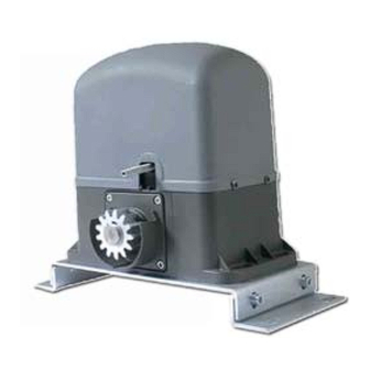
USER’S MANUAL MIG ____________________________________________________________________ 1. GENERAL OUTLINE Electromechanical operator designed to automate residential-type gates. operator keeps the gate blocked on closing and on opening, without needing an electric lock. The operator has no mechanical clutch. It must be controlled by an electronic control panel provided with torque setting. - Page 5 USER’S MANUAL MIG ____________________________________________________________________ - maximum temperature on the cable surface of +50° C - minimum temperature of -25° C Moreover, it must have a minimum section of 3 x 1.5 mm2 and, for the cable to hold correctly, it must be provided with an external sheath of Ø = 7.1 to 9.6 mm.
- Page 6 USER’S MANUAL MIG ____________________________________________________________________ POSITIONING FOR BASE PLATE prepare the sub structure in order to fix base plate, respecting approximately measures like Fig. 2 POSITIONING OF GEAR MOTOR Position the gear motors (Fig. 3) on the great plate (A), using the appropriate screws supplied.
- Page 7 USER’S MANUAL MIG ____________________________________________________________________ FIXING RACK AND END-RUN DEVICE Position the first element of rack cogwheel, previously unlocked, as in Fig. 5. Following fix the element to the gate, in the way you wish, by applying to it the other...
- Page 8 USER’S MANUAL MIG ____________________________________________________________________ Connect the control and safety devices in compliance with the previously mentioned electrical installation standards. The main automation components are: Control panel and incorporated receiver Pair of outside photocells Key selector Pair of inside photocells Blinker tuned in with antenna...
-
Page 9: Maintenance
USER’S MANUAL MIG ____________________________________________________________________ Any malfunction should be corrected immediately by a qualified specialist. Keep children at a safe distance from the field of action of the automation. THE CONTROLS With the automation the gate has a power driven opening and closing. The controls can come in various forms (i.e. -
Page 10: Manual Mode
USER’S MANUAL MIG ____________________________________________________________________ Check for the presence of power supply to the gear motor using a suitable instrument after opening or closing commands have been given. If the motor vibrates but does not turn, the causes could be the following: a) incorrect connection of the C common wire. - Page 11 USER’S MANUAL MIG ____________________________________________________________________ over 90° and make the manoeuvres you like. At the end of the operations, restore the lever in the starting position. CARATTERISTICHE MIG 400 MIG 600 MIG 1000 Supply (Vac 50Hz) Engine supply (Vac/Vdc) 24/220 Engine power...
- Page 12 USER’S MANUAL MIG ____________________________________________________________________ 11. ELECTRONIC EQUIPMENT L1 (220V) INTRODUCTION The electronic equipment Type S1R can be used to control one actuator for a sliding gate. The max. absorption of the device is 600W per 230V 50Hz. The set-up of the parameters must be carried out after the installation of all the equipment.
-
Page 13: Installation
USER’S MANUAL MIG ____________________________________________________________________ INSTALLATION Before making the electrical connections it is necessary to turn off the mains of 230V 50Hz and regulate the motor torque to a minimum. Use 0.5mm2 wires to make connections to the pushbuttons, photocells and 24V power supply. - Page 14 USER’S MANUAL MIG ____________________________________________________________________ M1 terminal board START Normally open pushbutton (opening / closing) STOP Normally closed pushbutton (stop) ST.P Normally open pushbutton (pedestrian opening) PHOTO Normally closed input external photocell SAFETY Normally closed safety contact L.S.C. Normally closed contact limit switch closing L.S.O.
- Page 15 USER’S MANUAL MIG ____________________________________________________________________ OPERATING MODES CONDOMINIUM AUTOMATIC: The gate is opened when the START button is pressed whether the gate is closed or being closed. The START command is ignored while the gate is being opened, whereas during the pause phase it makes the timing of this phase restart.
- Page 16 USER’S MANUAL MIG ____________________________________________________________________ There are two 5x20-size fuses on the board that protect the 230V line and the secondary of the transformer. The fuses have the following values: 230V line F1 = 5 A fast Secondary F2 = 630 mA fast Before replacing the fuses it is necessary to turn off the 230V mains power supply.
- Page 17 USER’S MANUAL MIG ____________________________________________________________________ (**) If comfort is enabled dip 6 don't cares (***) The function photocell retrigger makes the timing of the pause restart if the photocells are in use during the pause itself. After each mode change it is necessary to short circuit JR1 reset contacts for a few...
- Page 18 USER’S MANUAL MIG ____________________________________________________________________ REMOTE CONTROLS LEARNING The SR equipment is equipped with a built-in decoder able to memorize up to 128 rolling-code remote controls or one fixed-code remote controls. Start function In closed-gate mode, press the PROG.B button and hold it down until the TEST LED starts to flash.
-
Page 19: Dip Switch
USER’S MANUAL MIG ____________________________________________________________________ INSTALLATION SLIDING GATE TYPE TRIMMER • Trimmer TR1 DELAY as you need. • Trimmer TR2 TORQUE to the minimum. • Trimmer TR3 SK-CU as you need. • Trimmer TR4 BRAKE as you need. DIP SWITCH From 1 to 6 as you need. - Page 20 USER’S MANUAL MIG ____________________________________________________________________ CONNECTIONS ____________________________________________________________________________________ MATT di LIEVORE SRL Via Bianche 7 36010 Carre’ ( VI ) Tel. 0445 / 892223 Fax 0445 / 390346...
- Page 21 USER’S MANUAL MIG ____________________________________________________________________ 15. ELECTRONIC EQUIPMENT L1LW (24V) Firmware versione 1.02 JEXP1 ____________________________________________________________________________________ MATT di LIEVORE SRL Via Bianche 7 36010 Carre’ ( VI ) Tel. 0445 / 892223 Fax 0445 / 390346...
-
Page 22: Sliding Gate
USER’S MANUAL MIG ____________________________________________________________________ SETTINGS DIP 7 DIP 6 Operating mode SLIDING GATE Function Preflashing 3 SECONDS Enabled Disabled Condominium automatic Enabled Disabled Automatic closing Enabled Disabled Stop function Photocell Emergency button open Closing after photocell action Enabled Disabled Safety mode... - Page 23 USER’S MANUAL MIG ____________________________________________________________________ REMOTE CONTROLS LEARNING The SR equipment is equipped with a built-in decoder able to memorize up to 128 rolling-code remote controls or one fixed-code remote controls. Start function In closed-gate mode, press the P2 button and hold it down until the TEST LED starts to flash.
- Page 24 USER’S MANUAL MIG ____________________________________________________________________ Erasing of one learnt remote controls In closed-gate mode, press the P2 button and hold it pressed till when the TEST led starts to flash; don’t release the button and wait until the flash gets quicker; don’t release the button and wait until the flash gets very quick;...
- Page 25 USER’S MANUAL MIG ____________________________________________________________________ 3° input START: When you decide to start the slow-stroke phase, press START: the slow- stroke phase starts until the limit switch After 3 seconds gate starts opening 4° input START: gate stops at pedestrian point decided.
- Page 26 USER’S MANUAL MIG ____________________________________________________________________ CONNECTION M1 Opening if boom is down, or if boom is closing OPEN Opening if boom is down, stop during opening if DIP 2 OFF, closing if boom is START stopped, opening if boom is closing...
- Page 27 USER’S MANUAL MIG ____________________________________________________________________ CONNECTION M4 + LOCK OR LBC Active during opening/closing, fixed if boom stopped - LOCK OR LBC + FLASH Flashing during opening/closing, if DIP 1 ON preflashing, 3 sec before any action - FLASH + M1...
- Page 28 USER’S MANUAL MIG ____________________________________________________________________ WARNINGS Correct controller operation is only ensured when the data contained in the present manual are observed. The Company is not to be held responsible for any damage resulting from failure to observe the installation standards and the instructions contained in the present manual.
Need help?
Do you have a question about the 1000 and is the answer not in the manual?
Questions and answers