Table of Contents
Advertisement
Advertisement
Table of Contents

Related Manuals for Tibbo TPB2


Summary of Contents for Tibbo TPB2
- Page 1 Tibbo Programmable Hardware Manual Copyright Tibbo Technology...
-
Page 2: Table Of Contents
Pow er, Reset, PLL Control, and Mode Selection ................................23 Mechanical Dim ensions ................................24 Ordering Info and Specifications ................................26 EM1000 BASIC/C-programmable Ethernet Module ........................... 28 EM1000-00 and -01 ................................30 Detailed Device Info ................................31 General-purpose I/O Lines ................................ - Page 3 I2C/SPI Support (SSI Channels) ................................118 Square Wave Generator ................................118 Flash and EEPROM Memory ................................119 Real-time Clock (RTC) and Backup Battery ................................119 LEDs and LED Lines ................................119 External LCD Support ................................120 © Tibbo Technology Inc.
- Page 4 RS232/485 Port ............................... 175 LED Control ............................... 176 Ordering Info and Specifications ................................177 IB1005 and SB1005 (Digital I/O) ................................177 Terminal Blocks ................................178 Control Lines ................................180 Detailed Information ................................182 Opto-isolated Inputs ............................... 183 © Tibbo Technology Inc.
- Page 5 EM1000TEV ........................... 232 TEV-MB0 ................................233 TEV-KB0 ................................233 TEV-LBx Boards ................................235 TEV-LB0 ................................237 TEV-LB1 ................................239 TEV-LB2 ................................240 TEV-IBx Boards ................................242 TEV-IB0 ................................243 TEV-IB1 ................................244 Ordering Info ................................246 © Tibbo Technology Inc.
- Page 6 ................................248 EM500EV-IB0 ................................249 EM500EV-IB1 ................................250 EM500EV-IB2 ................................251 Ordering Info ................................252 Tibbo Project System (TPS) TPS: the General View ........................... 255 Tibbits ........................... 256 Tibbit Form Factors & Colors ................................256 M1 "Narrow " Tibbits ................................257 M2 "Wide"...
- Page 7 Smart LED Controller Configuration ............................... 376 #58, M1S: Tw o 24V NPN Isolated Open Collector Outputs ................................378 #59, M1S: Tw o 24V PNP Isolated Open Collector Outputs ................................380 Tibbo Project PCBs (TPPs) ........................... 381 © Tibbo Technology Inc.
- Page 8 Tiles, Sockets, Connectors, Controls ................................400 Netw ork Configuration ................................401 Firmw are Updates ................................402 Size 3 Linux Tibbo Project PCB (LTPP3), Gen 2 ................................405 Tiles, Sockets, Connectors, Controls ................................407 Plus1 (SP7021) CPU ................................408 Firmw are Updates ................................
- Page 9 ................................490 Setting Up and Testing Bus Probes ................................494 Setting Modbus IDs ................................494 Updating Probe Firm w are ................................495 Status LEDs ................................497 Outline Dim ensions ................................499 Ordering Info and Specifications ................................499 © Tibbo Technology Inc.
- Page 10 ................................503 Ordering and Specifications ................................504 Companion Products WA2000 ........................... 505 Connector Pin Assignm ent ................................507 Connecting WA2000 to Tibbo Devices ................................508 Status LED ................................509 Firm w are Upgrades ................................509 Mechanical Dim ensions ................................510 Ordering Info and Specifications ................................
- Page 11 Contents Ethernet Updates ........................... 544 BLE (Bluetooth Low-Energy) Updates ........................... 546 Prolonging and Estimating EEPROM Life Update history © Tibbo Technology Inc.
-
Page 12: Introduction
(your Company) wish to make use of any documentation or technical information published by TIBBO, and/or make use of any source code published by TIBBO, and/or consult TIBBO and receive technical support from TIBBO or any of its employees acting in an official or unofficial... - Page 13 PRODUCT COMBINATION. 2. BASIC/C-programmable devices ("PROGRAMMABLE DEVICES") manufactured by TIBBO can run a variety of applications written in Tibbo BASIC, Tibbo C, or a combination of the two ("BASIC APPLICATIONS"). Combining a particular PROGRAMMABLE DEVICE with a specific BASIC and/or C APPLICATION, either written by TIBBO or any third party, may potentially create a combinatorial end product ("END PRODUCT") that violates local rules, regulations, and/or infringes an...
- Page 14 Tibbo personnel) shall not be construed as obligatory to TIBBO in any way, shape or form. TIBBO may change or delay any of its plans and product roadmaps without prior notice, and shall not be held liable for such changes.
-
Page 15: Common Vs. Proprietary Knowledge
Google it. Example: Let's suppose Tibbo makes an embedded module that has a number of I/O lines, and these lines are of the CMOS type. Proprietary knowledge here is that I/O lines on the module are of the CMOS type. I need to tell you this, because if I don't tell you then you don't have any other way to find out (except through guessing or reverse-engineering my product). -
Page 16: Embedded Modules
· EM1202 · EM200* * The EM200 module is a dual-use device. For best results, use the EM1000 and EM1202 modules based on the new T1000 ASIC developed by Tibbo. EM2000 BASIC/C-programmable IoT Module Introduction The EM2000 is Tibbo's fastest, as well as the most powerful and versatile BASIC/C- programmable IoT module. - Page 17 TiOS, code, and file system). · 56 I/O lines (vs. 54 lines on the EM1000). · 4-channel ADC. · The ability to update TiOS firmware and compiled Tibbo BASIC/C app over-the-air (this requires the WA2000 and an iOS or Android device). Hardware features ·...
- Page 18 Ethernet LAN; or o Over-the-air (this requires the WA2000 and an iOS or Android device). · Tibbo BASIC/C application can be debugged through the Ethernet LAN (no additional debugging hardware is required). · CE- and FCC-certified. * Must be connected externally.
-
Page 19: Detailed Device Info
Detailed Device Info Note: "SPI connector" is now referred to as "wireless add-on port" See these topics for more information on various hardware facilities of the EM2000: · General-purpose I/O Lines · Wireless Add-on port, Wi-Fi Communications © Tibbo Technology Inc. - Page 20 RX, W1 input, and DATA input of the serial port 0. GPIO9/P1.1/TX0 General-purpose I/O line 9 (P1.1); (1,2) TX, W1 output, and DATA output of the serial port 0. GPIO10/P1.2/RX1 General-purpose I/O line 10 (P1.2); (1,2) © Tibbo Technology Inc.
- Page 21 General-purpose I/O line 43 (does not (1,2) belong to any 8-bit port); ADC input System ground. GPIO44 General-purpose I/O line 44 (does not (1,2) belong to any 8-bit port). GPIO25/P3.1 General-purpose I/O line 25 (P3.1). (1,2) © Tibbo Technology Inc.
- Page 22 (1,2) belong to any 8-bit port). DBGRX RX line of debug serial port. VCCB Backup power for the real-time counter; connect directly to the backup power source (1.8-3.3V range). DBGTX TX line of debug serial port. © Tibbo Technology Inc.
-
Page 23: General-Purpose I/O Lines
EM2000 powers up, all its I/O lines have their output buffers tri-stated (in other words, all I/O lines are configured as inputs). You need to explicitly enable the output buffer of a certain I/O line if you want this line to become an output. © Tibbo Technology Inc. -
Page 24: Wireless Add-On Port, Wi-Fi Communications
GPIO line and port manipulation on the EM2000 is about 7 times faster compared to the EM1000. I/O line control is described in detail in the documentation for the I/O (io.) object found inside the TIDE, TiOS, Tibbo BASIC, and Tibbo C Manual. -
Page 25: Ethernet Port Lines
I/O lines can be used for communicating with it. This is facilitated by several I/O mapping properties offered by the Wi-Fi (wln.) object. For more details on Wi-Fi communications see wln. object's documentation in the TIDE, TiOS, Tibbo BASIC, and Tibbo C Manual. Ethernet Port Lines 4.1.1.3 The Ethernet port of the EM2000 is of the 100/10BaseT type. -
Page 26: Serial Ports
Specifically, the EM1000 has AVCC lines, and the EM2000 does not. Pins 62 and 65, that used to be AVCC pins on the EM1000 are left unconnected on the EM2000 product (so it is OK if your board has these lines). - Page 27 DTR and DSR lines often found on RS232 ports are not controlled by the ser. object. It is the responsibility of your Tibbo BASIC/C application to take care of these lines. Therefore, you can choose what GPIO lines of the EM2000 will be used as DTR and DSR lines in your system.
-
Page 28: Wiegand And Clock/Data Circuit Examples
No additional circuitry is required to handle clock/data streams. For more information see the documentation for the serial (ser.) object found inside the TIDE, TiOS, Tibbo BASIC, and Tibbo C Manual. Wiegand and Clock/Data Circuit Examples In the Wiegand mode, the W0&1in input of the serial port must receive a logical AND of W0 and W1 output of attached Wiegand device. -
Page 29: Analog-To-Digital Converter (Adc)
The square wave generator can produce a square wave output on pin GPIO45/CO of the EM2000. This output is primarily intended for generating audio signals using buzzer and is covered in the beep (beep.) object — see the TIDE, TiOS, Tibbo BASIC, and Tibbo C Manual. -
Page 30: Real-Time Clock (Rtc)
Prolonging and Estimating EEPROM Life. Like all other flash memory devices on the market, flash ICs used in Tibbo products only allow for a limited number of write cycles. As the Wikipedia article on flash memory (https://en.wikipedia.org/wiki/Flash_memory) explains, modern flash ICs still suffer from comparatively low write endurance. -
Page 31: Led Lines
Status LEDs. Your Tibbo BASIC/C application can control red and green status LEDs, as well as up to four externally connected LED pairs through the pattern (pat.) object, which is documented in the TIDE, TiOS, Tibbo BASIC, and Tibbo C Manual. -
Page 32: External Keypad Support
To build a keypad you will need to have at least one return line. A sensible count of scan lines, however, starts from two! Having a single scan line is like having no scan lines whatsoever — you might just as well ground this single scan line, i.e. always keep it active: © Tibbo Technology Inc. - Page 33 Binary keypads (i.e. "keypads that output binary key codes") do not require scanning — they contain a (typically microcontroller-based) circuit that performs the scanning and outputs encoded binary codes of pressed keys. Such keypads are sometimes called "encoded keypads": © Tibbo Technology Inc.
-
Page 34: Power, Reset, Pll Control, And Mode Selection
— a poorly built circuit may affect EM2000 operation. We recommend that you use a switching power supply. For correct device operation, the VCCB line should not be left unconnected. You may connect this line to the backup battery, or main 3.3V power (see Real-time Counter). © Tibbo Technology Inc. -
Page 35: Mechanical Dimensions
· Low speed: 16MHz The clock speed can be changed programmatically, via the system (sys.) object. For more information see TIDE, TiOS, Tibbo BASIC, and Tibbo C Manual. Mode selection The function of the MD line is described in Setup Button (MD line). - Page 36 Additional height added by the supercapacitor ("-S" option devices only) Lead length Pin pitch Dimensions are for reference only. Tibbo assumes no responsibility for any errors in this Manual, and does not make any commitment to update the information contained herein. © Tibbo Technology Inc.
-
Page 37: Ordering Info And Specifications
"A" and "T" versions are not standard and cannot be ordered from our online store. Contact Tibbo if you wish to order EM2000 devices with "A" or "T" options. If the flash memory size is omitted, 1024K option is implied. - Page 38 Think the above table should contain additional data? Do not just assume that you know the answer — talk to Tibbo! Remember that the ultimate responsibility for all decisions you make regarding the use and the mode of use of Tibbo products lies with you, our Customer.
-
Page 39: Em1000 Basic/C-Programmable Ethernet Module
The EM1000 is also excellent for prototyping your projects -- its pin pitch is standard 2.54mm (0.1). The EM1000 is fully supported by TIDE software and a dedicated EM1000 platform that covers all hardware facilities of the module (see TIDE, TiOS, Tibbo BASIC, and Tibbo C Manual). - Page 40 Prototyping-friendly 2.54mm (100mil) pin pitch. · Operating temperature range: -40 ~ +70 C. · Firmware and compiled Tibbo BASIC/C app can be updated through the serial port or Ethernet LAN. · Tibbo BASIC/C application can be debugged through the Ethernet LAN (no additional debugging hardware is required).
-
Page 41: Em1000-00 And -01
(RC4, MD5, SHA-1), and more. EM1000-00 and -01 Small hardware changes were made to the EM1000 since its first release. Currently Tibbo supplies version "-01" of the module. The first version ever produced was "- 00". The main difference is in the Ethernet IC: the EM1000-...-00 used Davicom's DM9000 while the EM1000-...- 01 features newer DM9000A. -
Page 42: Detailed Device Info
Programmable Hardware Manual (PHM) Detailed Device Info Note: "SPI connector" is now referred to as "wireless add-on port" See these topics for more information on various hardware facilities of the EM1000: · General-purpose I/O Lines · Wireless Add-on port ·... - Page 43 General-purpose I/O line 17 (P2.1); (1,2,3) interrupt line 1. GPIO18/P2.2/IN General-purpose I/O line 18 (P2.2); (1,2,3) interrupt line 2. GPIO19/P2.3/IN General-purpose I/O line 19 (P2.3); (1,2,3) interrupt line 3. GPIO20/P2.4/IN General-purpose I/O line 20 (P2.4); (1,2,3) © Tibbo Technology Inc.
- Page 44 General-purpose I/O line 37 (P4.5). (1,2) GPIO36/P4.4 General-purpose I/O line 36 (P4.4). (1,2) GPIO39/P4.7 General-purpose I/O line 39 (P4.7). (1,2) GPIO38/P4.6 General-purpose I/O line 38 (P4.6). (1,2) Mode selection pin. <TEST PIN> Leave this pin unconnected. Reset line, active high. © Tibbo Technology Inc.
- Page 45 EM1000-...- 00: EM1000-...- 01: analog ground. EM1000-...- 01: AGND System ground. 3.3V power available on this pin. Do not connect to the power source. To avoid current loops, only use pin #60 to power the device. © Tibbo Technology Inc.
-
Page 46: General-Purpose I/O Lines
EM1000 devices. 40 of the I/O lines are combined into five 8-bit ports. The simplified structure of one I/O line of the EM1000 is shown on the circuit diagram below. Each line has an independent output buffer control. When the EM1000 powers up all its I/O lines have their output buffers tri-stated (in other words, all I/O lines are configured as inputs). -
Page 47: Wireless Add-On Port
Option "-A" EM1000 devices feature a 10-pin wireless add-on pin header. The pins on this header are identical to all other pins on the EM1000 and face the host PCB. This way the wireless port of the EM1000 can be connected to some other circuitry on the host PCB. -
Page 48: Ethernet Port Lines
The AVCC is an output! · Do not combine AVCC with the VCC (main power) pin. On the EM1000-...- 00 this is counter-productive, and on the EM1000-...- 01 this will apply wrong voltage to the AVCC pin. Doing so appears to be causing no immediate permanent damage to the EM1000-...- 01, but the circuit will not work and the effects of prolonged... - Page 49 Embedded Modules Once again, the EM1000-...- 00 is a legacy part that has been replaced with the EM1000-...- 01. In case you have already made the PCB based on the EM1000-...- 00 specifications and are not willing to change it, you can easily modify it to accommodate the EM1000-...- 01 (see diagram below):...
- Page 50 All of the above is based on the assumption that your host PCB was designed correctly and the AVCC output of the EM1000 is not joined together with the main VCC line. If you erroneously had AVCC and VCC combined together then you will need to separate them as well: pin AVCC outputs 2.5V on the EM1000-...- 01...
-
Page 51: Serial Ports
Serial Ports 4.2.2.4 The EM1000 has four serial ports that can work in one of the three modes: UART, Wiegand, or clock/data. All three modes are described in detail in the documentation for the serial (ser.) object found inside the TIDE, TiOS, Tibbo BASIC, and Tibbo C Manual. -
Page 52: Real-Time Counter
The disadvantage is that the supercapacitor is only able to sustain the RTC of the EM1000 for several days at most (about 6 days for the 4F supercapacitor of the EM1000-...-S), which may appear to be insufficient. -
Page 53: Led Lines
LED Lines 4.2.2.8 The EM1000 has four LED control lines -- SG, SR, EG, and EY. All lines have the same internal structure and the LEDs should be connected to these lines as shown on the schematic diagram below. Maximum load for each line is 10mA. - Page 54 The state of the PM pin at power-on or external reset (i.e. reset pulse on the RST line) defines whether the EM1000 will run with PLL on or off. To have the PLL on, leave the PM pin unconnected. To disable PLL and run at lower clock frequency, ground the PM pin.
-
Page 55: Mechanical Dimensions
Option "-A" EM1000 devices feature a 10-pin wireless add-on header (cross-section C). The pins on this header are identical to all other pins of the EM1000 and face the host PCB. This way the wireless add-on port of the EM1000 can be connected to some other circuitry on the host PCB. -
Page 56: Ordering Info And Specifications
Device numbering scheme is as follows: "A" and "T" versions are not standard and cannot be ordered from our online store. Contact Tibbo if you wish to order EM1000 devices with "A" or "T" options. 512K devices are no longer available. - Page 57 170mA with PLL on, 10BaseT mode 230mA with PLL on, 100BaseT mode Backup power voltage 2.2V - 3.3V (option without "-S" only) range (VCCB pin) Backup current (VCCB pin) 1mA when the EM1000 is running (3.3V on VCC) © Tibbo Technology Inc.
-
Page 58: Em1206 Basic/C-Programmable Ethernet Module
Think the above table should contain additional data? Do not just assume that you know the answer — talk to Tibbo! Remember that the ultimate responsibility for all decisions you make regarding the use and the mode of use of Tibbo products lies with you, our Customer. - Page 59 The EM1206 is fully supported by TIDE software and a dedicated EM1206 platform that covers all hardware facilities of the module (see TIDE, TiOS, Tibbo BASIC, and Tibbo C Manual). For convenient testing and evaluation Tibbo offers the EM1206EV evaluation board.
- Page 60 (LxWxH): 34.4 x 20.0 x 15.5mm. · Operating temperature range: -40 ~ +70 C. · Firmware and compiled Tibbo BASIC/C app can be updated through the serial port or Ethernet LAN. · Tibbo BASIC/C application can be debugged through the Ethernet LAN (no additional debugging hardware is required).
-
Page 61: Detailed Device Info
· LED Lines · Power, Reset, and Mode Selection Lines Main connector Pin # Function Description VCCB Backup power for the real-time counter. Do not connect to 3.3V directly! Mode selection pin. Reset line, active high. © Tibbo Technology Inc. - Page 62 Green status LED control line. Red status LED control line. (1,2) GPIO16/CO General-purpose I/O line 16 (does not belong to any port); square wave output line. (1,2) GPIO8/P1.0 General-purpose I/O line 8 (P1.0). (1,2) GPIO9/P1.1 General-purpose I/O line 9 (P1.1). © Tibbo Technology Inc.
-
Page 63: General-Purpose I/O Lines
Each I/O line has a weak pull-up resistor that prevents the line from floating when the output buffer is tri-stated. I/O line control is described in the io. object documentation (TIDE, TiOS, Tibbo BASIC, and Tibbo C Manual). © Tibbo Technology Inc. -
Page 64: Ethernet Port Lines
AVCC pin. Doing so appears to cause no immediate permanent damage to the EM1206, but the circuit will not work and the effects of prolonged over-voltage on the AVCC line are not known. © Tibbo Technology Inc. -
Page 65: Serial Ports
The rest of this flash memory is available to your Tibbo BASIC/C application and its data. Whatever memory space is left after the compiled application is loaded can be used as a flash disk (see fd. -
Page 66: Real-Time Counter
Prolonging and Estimating EEPROM Life. Like all other flash memory devices on the market, flash ICs used in Tibbo products only allow for a limited number of write cycles. As the Wikipedia article on flash memory (https://en.wikipedia.org/wiki/Flash_memory) explains, modern flash ICs still suffer from comparatively low write endurance. -
Page 67: Led Lines
Therefore, your battery-based backup circuit should be designed in a way that does not drain the battery while the Vcc is applied. Your Tibbo BASIC/C application can access the RTC through the rtc. object (see TIDE, TiOS, Tibbo BASIC, and Tibbo C Manual). - Page 68 EM1206 in reset while PLL frequency stabilizes. Unlike the EM1000, the EM12062 does not have a hardware pin to control the state of the PLL. On power up, the PLL is always enabled. Your Tibbo BASIC/C application can change the PLL mode programmatically.
-
Page 69: Onboard Leds
To aid the module in dissipating excess heat, a special heat- conductive sticker is applied to the top of the DM9000B. The protective paper of the sticker MUST BE REMOVED prior to installing the module on the host PCB. © Tibbo Technology Inc. -
Page 70: Mechanical Dimensions
PCB and interconnected by a number of large vias. Mechanical Dimensions Max. 33.4 Length W Max. 18.1 Width Max. 4.2 Height Aver 14.4 Length of the narrower part of the board Max. 16.7 Width at the narrower part of the board © Tibbo Technology Inc. -
Page 71: Ordering Info And Specifications
Min. Connector pin length All dimensions are in millimeters. Dimensions are for reference only. Tibbo assumes no responsibility for any errors in this Manual, and does not make any commitment to update the information contained herein. Ordering Info and Specifications Device numbering scheme is as follows: 512K devices are no longer available. - Page 72 230mA with PLL on, 100BaseT mode Nominal backup voltage 2.5V (VCCB pin) Backup current (VCCB pin) 1mA when the EM1000 is running (3.3V on VCC) 13uA when the EM1000 is not powered (0V on VCC) Operating temperature -40 to +70 degrees C...
-
Page 73: Em510 "Minimo" Basic/C-Programmable Iot Module
Think the above table should contain additional data? Do not just assume that you know the answer — talk to Tibbo! Remember that the ultimate responsibility for all decisions you make regarding the use and the mode of use of Tibbo products lies with you, our Customer. - Page 74 IoT designs. The EM510 is fully supported by TIDE software and a dedicated EM510 platform that covers all hardware facilities of the device (see TIDE, TiOS, Tibbo BASIC, and Tibbo C Manual). For convenient testing and evaluation Tibbo offers the EM510EV development system.
- Page 75 Over-the-air (this requires the WA2000 and an iOS or Android device). · Tibbo BASIC/C application can be debugged through the Ethernet LAN (no additional debugging hardware is required). · CE- and FCC-certified. * The EM510 does not support the combination of 7 bits/character mode and the "none"...
-
Page 76: Detailed Device Info
I/O pin assignment Pin # Function Description (1,2) GPIO0/P0.0/INT0 General-purpose I/O line 0 (P0.0); interrupt line 0. (1,2) GPIO1/P0.1/INT1 General-purpose I/O line 1 (P0.1); interrupt line 1; This pin is also used for interfacing to the external flash. © Tibbo Technology Inc. - Page 77 Positive power input, 3.3V nominal, +/- 5%, max. current consumption 110mA. Notes: 1. This line can serve as an RTS/Wout/cout line of a serial port. 2. This line can serve as a CTS/W0&1in/cin line of a serial port. © Tibbo Technology Inc.
-
Page 78: Serial Port And General-Purpose I/O Lines
Once the serial port is enabled, you lose the ability to control the TX line (set it HIGH or LOW) programmatically. Disabling the serial port (ser.enabled= 0- NO) does not alter the direction configuration of the TX line. © Tibbo Technology Inc. -
Page 79: Ethernet Port Lines
The fd. object is enabled in the Project Settings dialog of Tibbo IDE software. To enable, click on the Customize button (of the Project Settings dialog) and set "Flash disk (fd.) object"... -
Page 80: Flash And Eeprom Memory
The rest of this flash memory is available to your Tibbo BASIC/C application. The internal flash memory cannot be used as a flash disk. On the E510, the fd. object (see TIDE, TiOS, Tibbo BASIC, and Tibbo C Manual) requires an external flash IC. -
Page 81: Led Lines
The maximum load for each line is 10mA. For a small LED, a 330 Ohm series resistor will provide sufficient brightness. The SG and SR lines are used to control two status LEDs found on Tibbo products. These LEDs can show various flashing patterns indicating the current device state... -
Page 82: Power, Reset, And Mode Selection Lines
The function of the MD line is described in Setup Button (MD line). Power supply circuit Many power supply circuits will work well. The one below is being used by Tibbo. This circuit can handle input voltages in the 9-24V range. Notes: ·... -
Page 83: Mechanical Dimensions
Max. Module footprint dimension Aver. Module footprint dimension Dimensions are for reference only. Tibbo assumes no responsibility for any errors in this Manual, and does not make any commitment to update the information contained herein. Ordering Info and Specifications The EM510 "MiniMo" (R) device is only available in a single configuration and can be ordered as "EM510". - Page 84 Think the above table should contain additional data? Do not just assume that you know the answer — talk to Tibbo! Remember that the ultimate responsibility for all decisions you make regarding the use and the mode of use of Tibbo products lies with you, our Customer.
-
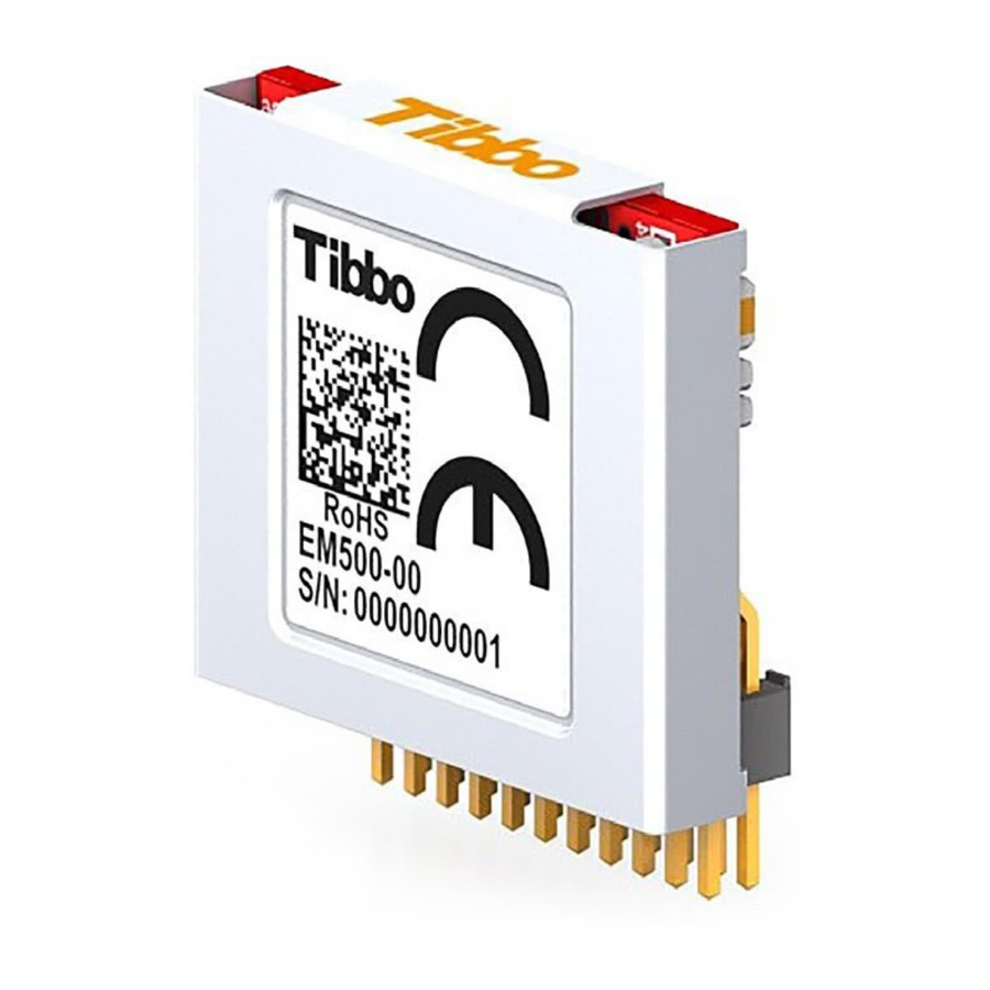
Page 85: Em500 "Minimo" Basic/C-Programmable Ethernet Module
The EM500 is fully supported by TIDE software and a dedicated EM500 platform that covers all hardware facilities of the module (see TIDE, TiOS, Tibbo BASIC, and Tibbo C Manual). For convenient testing and evaluation Tibbo offers the EM500EV development system. - Page 86 Dimensions (HxWxT): 16 x 18.5 x 6.5mm. · Operating temperature range: -40 ~ +70C. · Firmware and compiled Tibbo BASIC/C app can be updated through the serial port or Ethernet LAN. · Tibbo BASIC/C application can be debugged through the Ethernet LAN (no additional debugging hardware is required).
-
Page 87: Detailed Device Info
Embedded Modules * MiniMo is a registered trademark of Tibbo Technology. ** Fully supported with the exception of fd.copyfirmware; requires an externally connected flash Detailed Device Info See these topics for more information on various hardware facilities of the EM500: ·... - Page 88 2. This line can serve as an RTS/Wout/cout line of a serial port (provided that this does not interfere with any other function). 3. This line can serve as a CTS/W0&1in/cin line of a serial port (provided that this does not interfere with any other function). © Tibbo Technology Inc.
-
Page 89: Serial Port And General-Purpose I/O Lines
TX, RX, CTS, and CTS lines have different names and functions in the Wiegand and clock/data modes. Serial port operation is described in detail in the documentation for the serial (ser.) object found inside the TIDE, TiOS, Tibbo BASIC, and Tibbo C Manual. Additionally, see the Platform-dependent Programming Information section inside the EM500 platform documentation (same manual). -
Page 90: Flash And Eeprom Memory
The rest of this flash memory is available to your Tibbo BASIC/C application. The internal flash memory cannot be used as a flash disk. The fd. object (see TIDE, TiOS, Tibbo BASIC, and Tibbo C Manual) requires an external flash IC. -
Page 91: Led Lines
Prolonging and Estimating EEPROM Life. Like all other flash memory devices on the market, flash ICs used in Tibbo products only allow for a limited number of write cycles. As the Wikipedia article on flash memory (https://en.wikipedia.org/wiki/Flash_memory) explains, modern flash ICs still suffer from comparatively low write endurance. -
Page 92: Power, Reset, And Mode Selection Lines
Programmable Hardware Manual (PHM) The SG and SR lines are used to control two status LEDs found on Tibbo products. These LEDs can show various flashing patterns indicating the current device state (see Status LEDs). On the EM500, there is an added twist: the same pair of status LEDs also indicates the current Ethernet link status through LED brightness. - Page 93 The function of the MD line is described in Setup Button (MD line). Power supply circuit Many power supply circuits will work well. The one below is being used by Tibbo. This circuit can handle input voltages in the 9-24V range. Notes: ·...
-
Page 94: Mechanical Dimensions
Max. Module footprint dimension Aver. Module footprint dimension Dimensions are for reference only. Tibbo assumes no responsibility for any errors in this Manual, and does not make any commitment to update the information contained herein. Ordering Info and Specifications The EM500 "MiniMo"* device is only available in a single configuration and can be ordered as "EM500-00". - Page 95 Think the above table should contain additional data? Do not just assume that you know the answer — talk to Tibbo! Remember that the ultimate responsibility for all decisions you make regarding the use and the mode of use of Tibbo products lies with you, our Customer.
-
Page 96: Em1202 Basic/C-Programmable Ethernet Module
The EM1202 is fully supported by TIDE software and a dedicated EM1202 platform that covers all hardware facilities of the module (see TIDE, TiOS, Tibbo BASIC, and Tibbo C Manual). For convenient testing and evaluation Tibbo offers EM1202EV evaluation board. - Page 97 Power: 230mA @ 3.3V (100BaseT mode, PLL on). · Dimensions: 17.1x19.1x14.6mm. · Firmware and compiled Tibbo BASIC/C app can be updated through the serial port or Ethernet LAN. · Tibbo BASIC/C application can be debugged through the network and no additional debugging hardware, such as in-circuit emulator, is required.
-
Page 98: Detailed Device Info
Power, Reset, and Mode Selection Lines I/O pin assignment Pin # Function Description (1,2) GPIO28 General-purpose I/O line 28 (does not belong to any 8-bit port). (1,2) GPIO27 General-purpose I/O line 27 (does not belong to any 8-bit port). © Tibbo Technology Inc. - Page 99 1. GPIO10/P1.2/R General-purpose I/O line 10 (P1.2); (1,2) RX, W1, and din input of the serial port 1. GPIO18/P2.2/I General-purpose I/O line 18 (P2.2); (1,2,3) interrupt line 2. GPIO11/P1.3/T General-purpose I/O line 11 (P1.3); © Tibbo Technology Inc.
-
Page 100: General-Purpose I/O Lines
Simplified structure of one I/O line of the EM1202 is shown on the circuit diagram below. Each line has an independent output buffer control. When the EM1202 powers up all I/O lines have their output buffers tri-stated (in other words, all I/O © Tibbo Technology Inc. -
Page 101: Ethernet Port Lines
(or some other hardware block) is enabled. For details see Platform-dependent Programming Information inside the EM1202 platform documentation (TIDE, TiOS, Tibbo BASIC, and Tibbo C Manual). Each I/O line has a weak pull-up resistor that prevents the line from floating when the output buffer is tri-stated. -
Page 102: Serial Ports
The EM1202 has four serial ports that can work in one of the three modes: UART, Wiegand, or clock/data. All three modes are described in detail in the documentation for the serial (ser.) object found inside the TIDE, TiOS, Tibbo BASIC, and Tibbo C Manual. Additionally, see the Platform-dependent Programming Information section inside the EM1202 platform documentation (same manual). -
Page 103: Led Lines
Embedded Modules The rest of this flash memory is available to your Tibbo BASIC/C application and its data. Whatever memory space is left after the compiled application is loaded can be used as a flash disk (see fd. object documentation in the TIDE, TiOS, Tibbo BASIC, and Tibbo C Manual). -
Page 104: Power, Reset, And Mode Selection Lines
EM1202 in reset while PLL frequency stabilizes. Unlike the EM1000, the EM1202 does not have a hardware pin to control the state of the PLL. On power up, the PLL is always enabled. Your Tibbo BASIC/C application can change the PLL mode programmatically. - Page 105 Ideally, one should use an oscilloscope to see what sort of "square wave" the power supply generates, both at low and high input voltages, as well as light and heavy loads. There are no recipes here -- just try and see what works for your circuit. © Tibbo Technology Inc.
-
Page 106: Mechanical Dimensions
Min. Lead length Aver. 1.27 Pin pitch Dimensions are for reference only. Tibbo assumes no responsibility for any errors in this Manual, and does not make any commitment to update the information contained herein. Ordering Info and Specifications Device numbering scheme is as follows: 512K devices are no longer available. - Page 107 11.0592MHz with PLL off 88.4736MHz with PLL on Flash memory 512KBytes or 1024KBytes, entire memory minus 64KB is available to store Tibbo BASIC/C application and data. Typical write endurance is 100'000 write cycles per 256-byte sector. See the warning in...
-
Page 108: Em200
Think the above table should contain additional data? Do not just assume that you know the answer — talk to Tibbo! Remember that the ultimate responsibility for all decisions you make regarding the use and the mode of use of Tibbo products lies with you, our Customer. - Page 109 - External reset input. · Device firmware can be upgraded through the serial port or Ethernet. · Tibbo BASIC/C application can be uploaded and debugged through the Ethernet. Programming features · The following data types and related functions are supported: - Byte and char (occupy 1 byte);...
-
Page 110: Detailed Device Info
EM200C-02 devices: 3.3V EM200C-04 devices: 1.8V Ethernet port, positive line of the differential output signal pair. Ethernet port, negative line of the differential output signal pair. GPIO8 General-purpose I/O line 8. GPIO7 General-purpose I/O line 7. © Tibbo Technology Inc. -
Page 111: Ethernet Port Lines
Drawings below show circuit diagrams for both parts. Please, note the following: The Vout is an output that provides clean power for the magnetics circuitry, which is very sensitive to noise. On EM200C-02 devices, this pin outputs 3.3V; on EM200C-04 devices—1.8V. © Tibbo Technology Inc. - Page 112 PCB to surpass the maximum radiated emission limits stipulated by the FCC and CE regulations. Additionally, longer Ethernet lines on the PCB will make your board more susceptible to the ESD (electrostatic discharge) damage. © Tibbo Technology Inc.
-
Page 113: Serial Port And General-Purpose I/O Lines
The serial port of the EM200 can work in one of the three modes: UART, Wiegand, or clock/data. All three modes are described in detail in the documentation for the serial (ser.) object found inside the TIDE, TiOS, Tibbo BASIC, and Tibbo C Manual. Additionally, see the Platform-dependent Programming Information" section inside the EM200 platform documentation (same manual). -
Page 114: Power, Reset, And Mode Selection Lines
The function of the MD line is described in Setup Button (MD line). Power supply circuit Many power supply circuits will work well. The one below is being used by Tibbo. The circuit can handle input voltages in the 9-30V range. © Tibbo Technology Inc. -
Page 115: Mechanical Dimensions
R1 can be adjusted to achieve a better (cleaner) square wave signal on a particular PCB layout. There are no recipes here -- just try and see what works for your circuit. Mechanical Dimensions © Tibbo Technology Inc. -
Page 116: Ordering Info And Specifications
Aver. 28.0 Distance between lead rows Aver. 1.27 Pin pitch Dimensions are for reference only. Tibbo assumes no responsibility for any errors in this Manual, and does not make any commitment to update the information contained herein. Ordering Info and Specifications The EM200 has two sub-models in circulation- the EM200-00 and EM200-01. -
Page 117: Boards
Think the above table should contain additional data? Do not just assume that you know the answer — talk to Tibbo! Remember that the ultimate responsibility for all decisions you make regarding the use and the mode of use of Tibbo products lies with you, our Customer. - Page 118 As such, the EM2001 is equally suited to low-volume production devices and hobbyist projects alike. The EM2001 is fully supported by TIDE software. The board shares the same programming platform with the EM2000 module (see TIDE, TiOS, Tibbo BASIC, and Tibbo C Manual). EM2001 advantages over the EM1001 board...
- Page 119 Ethernet LAN; or o Over-the-air (requires the WA2000 and an iOS or Android device). · Tibbo BASIC/C application can be uploaded and debugged through the Ethernet LAN (no additional debugging hardware is required). · CE- and FCC-certified. * Must be connected externally.
- Page 120 · Variable Types: Byte, char, integer (word), short, dword, long, real, string, plus user-defined arrays and structures. · Function groups: String functions, trigonometric functions, date/time conversion functions, encryption/hash calculation functions (AES, RC4, MD5, SHA-1), and more. © Tibbo Technology Inc.
-
Page 121: Detailed Device Info
· Analog-to-digital Converter (ADC) · I2C/SPI Support · Square Wave Generator · Flash and EEPROM Memory · Real-time Clock (RTC) and Backup Battery · LEDs and LED Lines · External LCD Support · External Keypad Support © Tibbo Technology Inc. - Page 122 RX, W1 input, and DATA input of the serial port 3. GPIO15/P1.7/TX3 General-purpose I/O line 15 (P1.7); (1,2) TX, W1 output, and DATA output of the serial port 3. GPIO16/P2.0/INT0/CTS General-purpose I/O line 16 (P2.0); (1,2,3) interrupt line 0. © Tibbo Technology Inc.
- Page 123 (1,2) GPIO33/P4.1 General-purpose I/O line 33 (P4.1). (1,2) GPIO32/P4.0 General-purpose I/O line 32 (P4.0). (1,2) GPIO35/P4.3 General-purpose I/O line 35 (P4.3). (1,2) GPIO34/P4.2 General-purpose I/O line 34 (P4.2). (1,2) GPIO37/P4.5 General-purpose I/O line 37 (P4.5). (1,2) © Tibbo Technology Inc.
- Page 124 Leave this pin unconnected. GPIO52 Wireless add-on port, general-purpose I/O (1,2) line 52 (does not belong to any 8-bit port). GPIO53 Wireless add-on port, general-purpose I/O (1,2) line 53 (does not belong to any 8-bit port). © Tibbo Technology Inc.
-
Page 125: General-Purpose I/O Lines
(or some other hardware block) is enabled. For details see "Platform-dependent Programming Information inside the EM2000 platform documentation (TIDE, TiOS, Tibbo BASIC, and Tibbo C Manual). Each I/O line has a weak pull-up resistor that prevents the line from floating when the output buffer is tri-stated. -
Page 126: Wireless Add-On Port, Wi-Fi Communications
Nonetheless, it is always possible to connect the WA2000 by wires, in which case any combination of I/O lines can be used for communicating with it. For more details on Wi-Fi communications see TIDE, TiOS, Tibbo BASIC, and Tibbo C Manual (wln. object). - Page 127 DTR and DSR lines often found on RS232 ports are not controlled by the ser. object. It is the responsibility of your Tibbo BASIC/C application to take care of these lines. Therefore, you can choose what GPIO lines of the EM2000 will be used as DTR and DSR lines in your system.
-
Page 128: Wiegand And Clock/Data Circuit Examples
No additional circuitry is required to handle clock/data streams. For more information see the documentation for the serial (ser.) object found inside the TIDE, TiOS, Tibbo BASIC, and Tibbo C Manual. Wiegand and Clock/Data Circuit Examples In the Wiegand mode, the W0&1in input of the serial port must receive a logical AND of W0 and W1 output of attached Wiegand device. -
Page 129: Analog-To-Digital Converter (Adc)
The square wave generator can produce a square wave output on pin GPIO45/CO of the EM2001. This output is primarily intended for generating audio signals using buzzer and is covered in the beep (beep.) object — see the TIDE, TiOS, Tibbo BASIC, and Tibbo C Manual. -
Page 130: Flash And Eeprom Memory
Prolonging and Estimating EEPROM Life. Like all other flash memory devices on the market, flash ICs used in Tibbo products only allow for a limited number of write cycles. As the Wikipedia article on flash memory (https://en.wikipedia.org/wiki/Flash_memory) explains, modern flash ICs still suffer from comparatively low write endurance. -
Page 131: External Lcd Support
LOW. Take this into consideration when designing the LED circuit. Your Tibbo BASIC/C application can control red and green status LEDs, as well as up to four externally connected LED pairs through the pattern (pat.) object, which is documented in the TIDE, TiOS, Tibbo BASIC, and Tibbo C Manual. - Page 132 To build a keypad you will need to have at least one return line. A sensible count of scan lines, however, starts from two! Having a single scan line is like having no scan lines whatsoever — you might just as well ground this single scan line, i.e. always keep it active: © Tibbo Technology Inc.
- Page 133 Binary keypads (i.e. "keypads that output binary key codes") do not require scanning — they contain a (typically microcontroller-based) circuit that performs the scanning and outputs encoded binary codes of pressed keys. Such keypads are sometimes called "encoded keypads": © Tibbo Technology Inc.
-
Page 134: Power, Reset, Pll Control, And Mode Selection
Proper external reset is not required. The EM2001 has a reliable power-on reset circuit with brown-out detection. Optionally, you can connect a reset button or some other reset-generating circuit to the RST line of the EM2001. This will allow © Tibbo Technology Inc. -
Page 135: Mechanical Dimensions
· Low speed: 16MHz The clock speed can be changed programmatically, via the system (sys.) object. For more information see TIDE, TiOS, Tibbo BASIC, and Tibbo C Manual. Mode selection The function of the MD line is described in Setup Button (MD line). -
Page 136: Ordering Info And Specifications
Programmable Hardware Manual (PHM) Dimensions are for reference only. Tibbo assumes no responsibility for any errors in this Manual, and does not make any commitment to update the information contained herein. Ordering Info and Specifications To order, use the "EM2001" ordering code. - Page 137 Think the above table should contain additional data? Do not just assume that you know the answer — talk to Tibbo! Remember that the ultimate responsibility for all decisions you make regarding the use and the mode of use of Tibbo products lies with you, our Customer.
-
Page 138: Em1001 Basic/C-Programmable Iot Board
WA2000 Wi-Fi add-on, as well as an external LCD, keypad, buzzer, and many other peripheral components. Unlike the EM1000, the EM1001 us a self-sufficient board: it has a 12V-to-3.3V switching power regulator, RJ45 connector with magnetics, three LEDs, and the button. - Page 139 Operating temperature range: -40 ~ +70 C. · Firmware is upgradeable through the serial port or network. · Tibbo BASIC/C application can be uploaded and debugged through the Ethernet LAN (no additional debugging hardware is required). · CE- and FCC-certified.
-
Page 140: Detailed Device Info
Function Groups: 27 string functions, 8 date/time conversion functions, encryption/hash calculation functions (RC4, MD5, SHA-1), and more. Detailed Device Info See these topics for more information on various hardware facilities of the EM1001: · General-purpose I/O Lines © Tibbo Technology Inc. - Page 141 TX, W1, and dout output of the serial port 3. GPIO16/P2.0/INT General-purpose I/O line 16 (P2.0); (1,2,3) interrupt line 0. GPIO17/P2.1/INT General-purpose I/O line 17 (P2.1); (1,2,3) interrupt line 1. GPIO18/P2.2/INT General-purpose I/O line 18 (P2.2); (1,2,3) interrupt line 2. © Tibbo Technology Inc.
- Page 142 (1,2) GPIO34/P4.2 General-purpose I/O line 34 (P4.2). (1,2) GPIO37/P4.5 General-purpose I/O line 37 (P4.5). (1,2) GPIO36/P4.4 General-purpose I/O line 36 (P4.4). (1,2) GPIO39/P4.7 General-purpose I/O line 39 (P4.7). (1,2) GPIO38/P4.6 General-purpose I/O line 38 (P4.6). (1,2) © Tibbo Technology Inc.
- Page 143 3.3V power available on this pin. Do not connect to the power source. GPIO49 General-purpose I/O line 49 (does not belong to (1,2,4) any 8-bit port). No connection. GPIO50 General-purpose I/O line 50 (does not belong to (1,2,4) any 8-bit port). No connection. © Tibbo Technology Inc.
-
Page 144: General-Purpose I/O Lines
(or some other hardware block) is enabled. For details see "Platform-dependent Programming Information inside the EM1000 platform documentation (TIDE, TiOS, Tibbo BASIC, and Tibbo C Manual). Each I/O line has a weak pull-up resistor that prevents the line from floating when the output buffer is tri-stated. -
Page 145: Wireless Add-On Port
Nonetheless, it is always possible to connect the WA2000 by wires, in which case any combination of I/O lines can be used for communicating with it. For more details on Wi-Fi communications see TIDE, TiOS, Tibbo BASIC, and Tibbo C Manual (wln. object). -
Page 146: Serial Ports
The EM1001 has four serial ports that can work in one of the three modes: UART, Wiegand, or clock/data. All three modes are described in detail in the documentation for the serial (ser.) object found inside the TIDE, TiOS, Tibbo BASIC, and Tibbo C Manual. Additionally, see the Platform-dependent Programming Information section inside the EM1000 platform documentation (same manual). -
Page 147: Real-Time Counter And Backup Supercap
LOW. Take this into consideration when designing the LED circuit. Your Tibbo BASIC/C application can control red and green status LEDs, as well as up to four externally connected LED pairs through the pattern (pat.) object, which is documented in the TIDE, TiOS, Tibbo BASIC, and Tibbo C Manual. -
Page 148: Power, Reset, Pll Control, Md Button, And Mode Lines
(250mA @ 3.3V with PLL on vs. 130mA with PLL off). Main clock frequency also affects the baudrates of serial ports when in the UART mode, as well as the frequency produced by the square wave generator. © Tibbo Technology Inc. - Page 149 The Tibbo BASIC/C application can check the current PLL mode through the system (sys.) object (see TIDE, TiOS, Tibbo BASIC, and Tibbo C Manual). If the PLL mode needs to be changed the application must set the desired new mode and then perform an internal reset (again, through the system object).
-
Page 150: Mechanical Dimensions
Programmable Hardware Manual (PHM) Mechanical Dimensions Dimensions are for reference only. Tibbo assumes no responsibility for any errors in this Manual, and does not make any commitment to update the information contained herein. Ordering Info and Specifications Device numbering scheme is as follows: Hardware specifications ©... - Page 151 11.0592MHz with PLL off 88.4736MHz with PLL on Flash memory 1024KBytes, the entire memory minus 64KB is available for storing Tibbo BASIC/C application and data. Typical write endurance is 100'000 write cycles per 256-byte sector. See the warning in Flash and EEPROM Memory.
-
Page 152: Nb10X0 And Ib100X Boards
Think the above table should contain additional data? Do not just assume that you know the answer — talk to Tibbo! Remember that the ultimate responsibility for all decisions you make regarding the use and the mode of use of Tibbo products lies with you, our Customer. - Page 153 Ordering any "NB" or "IB" board also gets you an LED board and LC1000 cable, which will come attached to said "NB" or "LB" board. Tibbo NB10x0 and IB100x boards can be used "as is" or with a stylish, industrial- grade housing -- the...
-
Page 154: Nb10X0 Network Boards
LB1000 come assembled together and interconnected by the LC1000 cable. Additionally, the NB1000 comes with the IC1000 interboard cable. Therefore, you don't need to order the LB1000, LC1000, or IC1000 separately when purchasing the NB1000 board. © Tibbo Technology Inc. -
Page 155: Nb1000 Connectors And Controls
APR-P0008 (APR-P0009, or APR-P0010) power adaptor supplied by Tibbo or similar adaptor. On the power jack, the ground is "on the outside", as shown on the figure below. Another way to connect power is through the power terminals located next to the power jack. -
Page 156: Ethernet Jack
EM1000 onboard the NB1000 to run at full speed (88.4736MHz). Close the jumper if you want the EM1000 to run at 1/8th the full speed (11.0592MHz). Notice, that the jumper state is only recognized after the power-up or external reset (caused by pressing the reset button). The PLL mode can also be changed programmatically. -
Page 157: External Led Control
Boards These are yellow and green LEDs connected to the EY and EG pins of the EM1000. Further information on status LEDs can be found in Status LEDs. External LED Control The NB1000 is intended to be used with the LB1000 board. -
Page 158: Buzzer
The buzzer of the NB1000 is connected to the GPIO45/CO line of the onboard EM1000. Your application can control the buzzer through the "beeper" (beep.) object (see TIDE, TiOS, Tibbo BASIC, and Tibbo C Manual). Recommended value for the beep.divider property is 21600. Ordering Info and Specifications... -
Page 159: Nb1010 Board
Other details EM1000-1024K-S specification All specifications are subject to change without notice and are for reference only. Tibbo assumes no responsibility for any errors in this Manual, and does not make any commitment to update the information contained herein. NB1010 Board 5.3.1.2... -
Page 160: Nb1010 Connectors And Controls
APR-P0008 (APR-P0009, or APR-P0010) power adaptor supplied by Tibbo or similar adaptor. On the power jack, the ground is "on the outside", as shown on the figure below. Another way to connect power is through the power terminals located next to the power jack. -
Page 161: Ethernet Jack
This jumper selects the serial port of the NB1010 that will be used for serial firmware upgrades. When the jumper is opened, serial port 1 is used (TX0 (#17) and RX0 (#19) lines on the IC1000 interboard cable). Interface boards typically implement serial port 1, thus making serial firmware upgrades possible. © Tibbo Technology Inc. -
Page 162: External Led Control
LOW and this turns all LEDs ON. GPIO47 is a clock line- a positive (LOW-to-HIGH) transition on this line "shifts in" the data on the GPIO48 line. The circuit that controls the LEDs is shown below. LED numbers correspond to numbers shown on LB100x drawing. © Tibbo Technology Inc. - Page 163 LED2 LED3 LED4 LED5 cycle HIGH HIGH As you can see, each clock cycle sets a new state for LED1 which directly corresponds to the state of the Data line, and shifts all previous LED states. © Tibbo Technology Inc.
-
Page 164: Buzzer
TiOS, Tibbo BASIC, and Tibbo C Manual). Before such data communications can take place, the Wi-Fi interface must be properly configured. This is jointly achieved by the wln. object and WLN library (again, see TIDE, TiOS, Tibbo BASIC, and Tibbo C Manual). -
Page 165: Ordering Info And Specifications
GPIO line manipulation is performed using the io. object (see TIDE, TiOS, Tibbo BASIC, and Tibbo C Manual). Another object -- ser. -- is responsible for serial port communications. Actual data exchange via the GPRS module is the domain of the sock. -
Page 166: Ib100X Interface Boards
Think the above table should contain additional data? Do not just assume that you know the answer — talk to Tibbo! Remember that the ultimate responsibility for all decisions you make regarding the use and the mode of use of Tibbo products lies with you, our Customer. -
Page 167: Ib1000, Ib1002, And Ib1003 (4 Serial Ports)
These boards can optionally be used with the TB1000 terminal block adaptor. Connectors and Headers IB1000/2/3 boards carry two DB9-M connectors onboard. Two additional connectors attach (via cables) to two 2x5 pin headers located on the boards. © Tibbo Technology Inc. - Page 168 RX- (input) TX (output) TX+ (output) TX+ (output) DTR (output) TX- (output) TX- (output) SYSTEM GROUND SYSTEM GROUND SYSTEM GROUND DSR (input) RX+ (input) RX+ (input) RTS (output) RTS+ (output) CTS (input) CTS+ (input) CTS- (input) © Tibbo Technology Inc.
-
Page 169: Serial Ports
NB10x0 network board). Tibbo BASIC/C application running on the EM1000 works with serial ports through a "serial" (ser.) object (see TIDE, TiOS, Tibbo BASIC, and Tibbo C Manual). The object takes care of the data transmission through the TX line as well as data reception through the RX line. - Page 170 HIGH for data output. This is achieved by setting the ser.dircontrol= 0- PL_SER_DCP_LOWFORINPUT. Do not forget that all lines of the EM1000 are configured as inputs by default. Any line that should work as an output must be configured as such. This is done through the io.enabled property of the i/o object.
-
Page 171: Led Control
To turn the LED on, set the corresponding line LOW. Do not forget to configure LED control lines as outputs. This is done through the io.enabled property of the .io object (see TIDE, TiOS, Tibbo BASIC, and Tibbo C Manual). LED #, color... -
Page 172: Ib1004 And Sb1004 (Analog I/O)
Think the above table should contain additional data? Do not just assume that you know the answer — talk to Tibbo! Remember that the ultimate responsibility for all decisions you make regarding the use and the mode of use of Tibbo products lies with you, our Customer. -
Page 173: Terminal Blocks
There are nine terminals in each terminal block. · A/D inputs are grouped into terminal blocks 1 and 2. · D/A outputs are on terminal block 3. · Relay outputs and the serial port are on terminal block 4. © Tibbo Technology Inc. - Page 174 A/D GROUND (isolated from the rest of the device) Terminal block 2 Terminal # Function A/D channel 8, negative input (-) A/D channel 8, positive input (+) A/D channel 7, negative input (-) A/D channel 7, positive input (+) © Tibbo Technology Inc.
-
Page 175: Control Lines
(located on the NB10x0 network board) are used to control the IB1004 + SB1004. In the tables below, "output" means an output of the EM1000, and "input" means an input of the EM1000. A/D converter control For more information see Converter. - Page 176 Relay 1 control: GPIO36 (output) HIGH (or input*) - relay LOW - relay on RELAY2 Relay 2 control: GPIO37 (output) HIGH (or input*) - relay LOW - relay on *GPIO line configured as input (default state) © Tibbo Technology Inc.
-
Page 177: Detailed Information
· Two low-current mechanical relays (both normally-opened and normally-closed terminals are provided). · RS232/485 port (RX/TX signals for the RS232, TX/RX+ and TX/RX- for the RS485). · Control lines for 8 LEDs on the LB1001 board. © Tibbo Technology Inc. -
Page 178: A/D Converter
A/D channel 7, positive input (+) A/D channel 6, negative input (-) A/D channel 6, positive input (+) A/D channel 5, negative input (-) A/D channel 5, positive input (+) A/D GROUND (isolated from the rest of the device) © Tibbo Technology Inc. - Page 179 A/D control lines Nine lines of the EM1000 (located on the NB10x0 network board) control the A/D converter. In the table below, "output" means an output of the EM1000, and "input" means an input of the EM1000: Line Function Corresponding IC1000...
- Page 180 · Place the value of the most significant bit of the configuration word on the DO line. · Set the CLOCK line HIGH. · Set the CLOCK line LOW. This will conclude the first clock pulse. © Tibbo Technology Inc.
- Page 181 The calibration takes time. To determine when the calibration is over, poll the DI line after writing to the configuration register: © Tibbo Technology Inc.
- Page 182 Remember that the "effective resolution" discussed above has nothing to do with the number of bits you are supposed to read from the converter. This number is either 24 or 16, depending on the WL bit of the configuration register. © Tibbo Technology Inc.
-
Page 183: D/A Converter
All D/A-related lines are available on a 9-pin terminal block #3: Terminal # Function D/A channel 4, current output D/A channel 4, voltage output D/A channel 3, current output D/A channel 3, voltage output D/A channel 2, current output D/A channel 2, voltage output © Tibbo Technology Inc. - Page 184 D/A control Four lines of the EM1000 (located on the NB10x0 network board) control the D/A converter. In the table below, "output" means an output of the EM1000, and "input" means an input of the EM1000: Line Function Correspondin IC1000 cable...
-
Page 185: Relays
Relay outputs are on terminal block #4. Both normally closed and normally opened lines are provided for each relay. Terminal # Function Relay 2, normally opened line Relay 2, normally closed line Relay 2, common line © Tibbo Technology Inc. -
Page 186: Rs232/485 Port
NB10x0 network board) control the relays. On power up, all EM1000 lines are configured as inputs and pulled up internally, keeping relays off. To turn the relay on, set the corresponding control line LOW. Naturally, you need to configure these GPIO lines as outputs in order to be able to control the relays. -
Page 187: Led Control
HIGH (or input*) - LED off LOW - LED on LED #, color Corresponding IC1000 cable line EM1000 I/O (LB1001) #8, red GPIO24 #7, green GPIO25 #6, red GPIO26 #5, green GPIO27 #4, red GPIO28 #3, green GPIO29 © Tibbo Technology Inc. -
Page 188: Ordering Info And Specifications
Think the above table should contain additional data? Do not just assume that you know the answer — talk to Tibbo! Remember that the ultimate responsibility for all decisions you make regarding the use and the mode of use of Tibbo products lies with you, our Customer. -
Page 189: Terminal Blocks
The IB1005 and the SB1005 have four terminal blocks between them. There are nine terminals in each block. · serial port sensor input lines are grouped into terminal blocks 1 and 2. · relay outputs are on terminal blocks 3 and 4. © Tibbo Technology Inc. - Page 190 Serial port: RX (RS232); TX/RX- (RS485) Serial port: TX (RS232); TX/RX+ (RS485) SYSTEM (COMMON) GROUND Terminal block 2 Terminal # Function Sensor 8, positive line (+) Sensor 8, negative line (-) Sensor 7, positive line (+) © Tibbo Technology Inc.
-
Page 191: Control Lines
(located on the NB10x0 network board) are used to communicate with the IB1005 + SB1005. In the tables below, "output" means an output of the EM1000, and "input" means an input of the EM1000. Opto-isolated inputs For more information see Opto-isolated Inputs. - Page 192 Relay 2 control GPIO33 RELAY3 (output) Relay 3 control GPIO34 RELAY4 (output) Relay 4 control GPIO35 RELAY5 (output) Relay 5 control GPIO36 RELAY6 (output) Relay 6 control GPIO37 *GPIO line configured as input (default state) RS232/485 port control © Tibbo Technology Inc.
-
Page 193: Detailed Information
(both normally-opened and normally-closed terminals are provided). · RS232/485 port (RX/TX signals for the RS232, TX/RX+ and TX/RX- for the RS485). · Control lines for 8 LEDs on the LB1001 board (the board must be ordered separately). © Tibbo Technology Inc. -
Page 194: Opto-Isolated Inputs
The state of inputs is available on 8 general-purpose I/O (GPIO) lines of the EM1000 module (located on the NB10x0 network board). The EM1000 can check GPIO line state through the I/O (io.) object -- see TIDE, TiOS, Tibbo BASIC, and Tibbo C Manual for details. © Tibbo Technology Inc. - Page 195 Wiegand or clock/data readers. These channels are wired into the serial ports 1 and 2 of the EM1000. The serial ports of the module have a unique ability to decode the Wiegand and clock/data streams so processing the reader data is very simple.
-
Page 196: Relays
NB10x0 network board) control the relays. On power up, all EM1000 lines are configured as inputs and pulled up internally, keeping relays off. To turn the relay on, set the corresponding control line LOW. Naturally, each relay line must be configured as output. -
Page 197: Rs232/485 Port
IC1000 cable line EM1000 I/O GPIO8/RX0 RX (input) Receive line of the serial port GPIO9/TX0 TX (output) Transmit line of the serial port GPIO44 MODE Mode selection: (output) HIGH - RS485 LOW (or input*) - RS232 © Tibbo Technology Inc. -
Page 198: Led Control
Also included is the TB1005 test board. SB1005 The SB1005 supplementary board. Order this board "in parallel" with the IB1005. Note: the IB1005 and SB1005 plug into each other. No soldering is required to interconnect them. © Tibbo Technology Inc. -
Page 199: Lb100X Led Boards
Think the above table should contain additional data? Do not just assume that you know the answer — talk to Tibbo! Remember that the ultimate responsibility for all decisions you make regarding the use and the mode of use of Tibbo products lies with you, our Customer. - Page 200 "I/O" (io.) object found inside the TIDE, TiOS, Tibbo BASIC, and Tibbo C Manual. These LED's can also be used to play patterns generated by the ("pattern") .pat object. Correct "mapping" is required for this to work -- see object documentation for details.
-
Page 201: Cable Data
Controlled by the GPIO31 of the EM1000 (pin 32 on the interboard connector header). Note 1. This resistor's value is 0 because there is another resistor connected in series with the EM1000's GPIO line and located on the NB10x0 board. Cable data The following standard cables are supplied: ·... -
Page 202: Lc1000 Led Board Cable
"IB" boards. Connector pin assignment is shown below. LED numbers correspond to the numbers shown on the mechanical drawing of the LB100x. Pin #1 position of the connector is also shown on the drawing. Pin # Function Description 3.3V power from the "NB" ("IB"). © Tibbo Technology Inc. -
Page 203: Mechanical Data
50-pin header is on the right, while the LB1000 mounting holes are on the left. On the "NB" boards, the pin header is on the left, while the mounting holes are located on the right. © Tibbo Technology Inc. - Page 204 Distance to the board mounting hole Aver. Distance to the board mounting hole Aver. 22.0 Distance to the LB100x mounting hole Aver. Distance to the LB100x mounting hole Aver. 50.3 Distance to the LB100x mounting hole © Tibbo Technology Inc.
-
Page 205: Sb100X Board Dimensions
LB100x mounting hole dimension Aver. LB100x mounting hole, copper area diameter Dimensions are for reference only. Tibbo assumes no responsibility for any errors in this Manual, and does not make any commitment to update the information contained herein. SB100x Board Dimensions 5.3.5.2... - Page 206 No-component zone height Aver. Mounting hole diameter Aver. Distance to the board mounting hole Aver. Distance to the board mounting hole Max. 19.0 Header & interboard cable connector height Aver. 18.5 Gap between the IB100x and SB100x boards* © Tibbo Technology Inc.
-
Page 207: Lb100X Board Dimensions
* This is the standard gap; it will "happen" automatically when the boards are used inside the DS10xx housing. Dimensions are for reference only. Tibbo assumes no responsibility for any errors in this Manual, and does not make any commitment to update the information contained herein. LB100x Board Dimensions 5.3.5.3... - Page 208 Distance from the board surface to the LED center m8 Max. LED height with respect to the board surface Aver. 3.5 Gap between the LB100x and the bottom side of the NB10x0 (IB100x) Max. LED diameter © Tibbo Technology Inc.
-
Page 209: Ds1206N
(see below). The DS1206N is fully supported by TIDE software and a dedicated DS1206 platform that covers all hardware facilities of the board (see TIDE, TiOS, Tibbo BASIC, and Tibbo C Manual). This product ships preloaded with a fully functional serial-over-IP application. - Page 210 Superior upgrade to the EM1202EV board. · Based on a high-performance purpose-built 88-MHz T1000 ASIC. · Powered by Tibbo OS (TiOS). · 10/100BaseT auto-MDIX Ethernet port (automatic detection of "straight" and "cross" cables). · Up to 3.5 serial channels: - DS1206N-RS: RS232 port (DB9M connector);...
- Page 211 - DS1206N-TS: direct 3.3V input (must be regulated to +/- 5%). · Board dimensions: 52.6x38.0mm. · Firmware and Tibbo BASIC/C application are upgradeable through the serial port or network. · Tibbo BASIC/C application can be debugged through the network and no additional debugging hardware, such as in-circuit emulator, is required.
-
Page 212: Ds1206N Hardware
APR-P0011, APR-P0012, or APR-P0013 power adaptor supplied by Tibbo or similar adaptor with 12V nominal output voltage. Adaptor current rating should be at least 500mA. On the power jack, the ground is "on the outside", as shown on the figure below. -
Page 213: Ethernet Port
Tibbo BASIC/C application, enable (configure as output) line PL_IO_NUM8_PWROUT and then set this line to HIGH. Additional programming information can be found in TIDE, TiOS, Tibbo BASIC, and Tibbo C Manual (see i.o object and DS1206 platform documentation). -
Page 214: Multi-Channel Serial Port
For more information on serial ports and I/O lines of the DS1206N see ser. and io. object manuals (TIDE, TiOS, Tibbo BASIC, and Tibbo C Manual). Serial-over-IP application offered by Tibbo defines 15 "mapping options", or ways in which available I/O lines are utilized. These are presented in the table below:... - Page 215 CTS, and RTS lines, one more channel with just RX and TX lines, and yet another channel with a single RX line. The TX line is "missing" because, once again, there are only three outputs available. This is why this line is shown in grey lowercase (tx). © Tibbo Technology Inc.
-
Page 216: Flash And Eeprom Memory
The rest of this flash memory is available to your Tibbo BASIC/C application and its data. Whatever memory space is left after the compiled application is loaded can be used as a flash disk (see fd. -
Page 217: Mechanical Dimensions
40.5 Distance from the front edge of the PCB to the LEDs n4 Aver 47.0 Distance from the front edge of the PCB to the horizontal centerline of the TTL interface connector (present on the DS1202N-TM and "-TS" only) n5 Aver 50.1 PCB outline dimension © Tibbo Technology Inc. -
Page 218: Ordering Info And Specifications
"TS" version: TTL serial port on the pin header connector, direct 3.3V power input. "TM" and "TS" versions are not standard and cannot be ordered from our online store. Contact Tibbo if you wish to order DS1206B devices in "TM" or "TS" configurations. Examples of valid model numbers... - Page 219 Think the above table should contain additional data? Do not just assume that you know the answer — talk to Tibbo! Remember that the ultimate responsibility for all decisions you make regarding the use and the mode of use of Tibbo products lies with you, our Customer.
-
Page 220: Em1202Ev
(see TIDE, TiOS, Tibbo BASIC, and Tibbo C Manual). The EM1202 platform can be used with the board as well. This product ships preloaded with a fully functional serial-over-IP application. Written in Tibbo BASIC/C, the application is compatible with Tibbo Device Server Toolkit software, comes with full source codes, and can be modified by the user. - Page 221 - EM1202EV-RS and "-TM": onboard regulator, 10-24V input range; - EM1202EV-TS: direct 3.3V input (must be regulated to +/- 5%). · Board dimensions: 52.6x38.0mm. · Firmware and Tibbo BASIC/C application are upgradeable through the serial port or network. © Tibbo Technology Inc.
-
Page 222: Em1202Ev Hardware
Programmable Hardware Manual (PHM) · Tibbo BASIC/C application can be debugged through the network and no additional debugging hardware, such as in-circuit emulator, is required. · Also available as a DS1202 (EM1202EV-RS board with housing). Programming features · Variable Types: Byte, char, integer (word), short, dword, long, real, string, plus ser-defined arrays and structures. -
Page 223: Power Arrangement
APR-P0012, or APR-P0013 power adaptor supplied by Tibbo or similar adaptor with 12V nominal output voltage. Adaptor current rating should be at least 500mA. On the power jack, the ground is "on the outside", as shown on the figure below. -
Page 224: Multi-Channel Serial Port
CTS or DSR. The spare input cannot work as an RX line. This input is not used by the serial-over-IP application supplied by Tibbo and will be largely omitted from further discussion. Your Tibbo BASIC/C application can always use this extra input if you require it. - Page 225 3.3V Output to external device Input from external device *Not used in Tibbo serial-over-IP application. Your Tibbo BASIC/C program can use this line if needed. Serial-over-IP application offered by Tibbo defines 15 "mapping options", or ways in which available I/O lines are utilized ("spare" input is not used or shown). These are...
-
Page 226: Additional Information On Serial Port Lines
This topic contains information related to programming of the EM1202EV. It assumes that you are familiar with Tibbo BASIC/C and the concept of "platforms". Everything you need to know regarding this can be found in TIDE, TiOS, Tibbo BASIC, and Tibbo C Manual. -
Page 227: Flash And Eeprom Memory
The rest of this flash memory is available to your Tibbo BASIC/C application and its data. Whatever memory space is left after the compiled application is loaded can be used as a flash disk (see fd. -
Page 228: Mechanical Dimensions
EM1202EV-RS only) n4 Aver 47.0 Distance from the front edge of the PCB to the horizontal centerline of the TTL interface connector (present on the EM1202EV-TM and "-TS" only) n5 Aver 50.1 PCB outline dimension © Tibbo Technology Inc. -
Page 229: Ordering Info And Specifications
"TS" version: TTL serial port on the pin header connector, direct 3.3V power input. "TM" and "TS" versions are not standard and cannot be ordered from our online store. Contact Tibbo if you wish to order DS1206B devices in "TM" or "TS" configurations. Examples of valid model numbers... - Page 230 Think the above table should contain additional data? Do not just assume that you know the answer — talk to Tibbo! Remember that the ultimate responsibility for all decisions you make regarding the use and the mode of use of Tibbo products lies with you, our Customer.
-
Page 231: Em1206Ev
LEDs can be found in Status LEDs. · Buzzer (connected to the line of the EM1206). · Supercapacitor (backup power source) for the of the EM1206. Board structure is further illustrated by this block diagram: © Tibbo Technology Inc. -
Page 232: Wireless Add-On Connector
This connector is used to plug in an optional wireless add-on, such as the WA2000 Wi-Fi add-on, as well as other add-on modules that may be released by Tibbo in the future. The connector has 10 pins, as shown on the drawing below. Apart from the ground and Vcc (3.3V) lines, there are eight I/O lines that are connected directly to port 1... -
Page 233: Main And Backup Power
Use APR-P0011, APR-P0012, or APR-P0013 power adaptor supplied by Tibbo or a similar adaptor with 12V nominal output voltage. Adaptor current rating should be at least 500mA. On the power jack, the ground is "on the outside", as shown on the figure below. -
Page 234: Multi-Channel Rs232 Port And Expansion Connector
RS232 transceiver IC. The IC used on the EM1206EV board implements three outputs and four inputs. Therefore, only seven I/O lines of the EM1206 are connected to the RS232 port of the EM1206EV board. © Tibbo Technology Inc. - Page 235 For more information on serial ports and I/O lines of the EM1206 see ser. and io. object manuals (TIDE, TiOS, Tibbo BASIC, and Tibbo C Manual). Serial-over-IP application offered by Tibbo defines 15 "mapping options", or ways to utilize the available I/O lines. These are presented in the table below:...
- Page 236 RX line. The TX line is "missing" because, once again, there are only three outputs available on the RS232 port. This is why this line is shown in grey lowercase (tx). This line, of course, is present and available on the expansion connector. © Tibbo Technology Inc.
-
Page 237: Em120/Em200-Ev
Use APR-1014, APR-1015A, or APR-1018A power adaptor supplied by Tibbo or similar adaptor with 12V nominal output voltage. Adaptor current rating should be at least 500mA. On the power jack, the ground is "on the outside", as shown on the figure below. -
Page 238: Ethernet Port Pin Assignment
<No connection> <No connection> <No connection> <No connection> RS232 Port Pin Assignment DB9M RS232 connector has the following pin assignment: <No connection> RX (input) TX (output) DTR (output) Ground DSR (input) RTS (output) CTS (input) <No connection> © Tibbo Technology Inc. -
Page 239: Expansion Connector Pin Assignment
RS232 transceiver. When the jumper is opened you can use the RX pin on the expansion connector to supply a TTL RX signal from your own external board. Figure below illustrates this. Maximum load for all CMOS-type lines (P0, P1, ... RX, TX...) is 10mA. © Tibbo Technology Inc. -
Page 240: Development Systems
Programmable Hardware Manual (PHM) Development Systems The following development systems are currently being offered by Tibbo: · EM2000EV · EM1000EV · EM1000TEV · EM500EV/EM510EV EM2000EV The EM2000EV is a low-cost board for evaluating the EM2000 BASIC/C- programmable IoT Module (the module is not included with the board and must be purchased separately). - Page 241 MD button. · Three LEDs: § SR (status red) and SG (status green) LEDs connected to SR and SG lines of the EM2000; § EY (Ethernet yellow) LED connected to the EY line of the EM2000. © Tibbo Technology Inc.
-
Page 242: Em1000Ev
Programmable Hardware Manual (PHM) EM1000EV The EM1000-EV Evaluation System offers a convenient way of testing the EM1000 BASIC/C-programmable embedded module. The board features the following components: · Metal base. · NB1000 network board with the EM1000 module (EM1000-512K-ST) installed on a socket. -
Page 243: Em1000Tev
Development Systems EM1000TEV The EM1000-TEV development system has been designed to aid you in developing data terminals, data collection devices, and control equipment based on the EM1000 embedded module. Hence, the abbreviation: "TEV" stands for "terminal evaluation". The EM1000-TEV includes the following boards: ·... -
Page 244: Tev-Mb0
The TEV-MB0 is a motherboard that has the EM1000 module (EM1000-512K-ST) installed on it. The EM1000 is installed on a socket. Schematic diagram of the TEV- MB0 board can be found on Tibbo website. The TEV-MB0 motherboard also features the following: ·... - Page 245 Required initialization code in Tibbo BASIC/C application This section assumes that you are familiar with Tibbo BASIC/C and TIDE software. These are documented in the TIDE, TiOS, Tibbo BASIC, and Tibbo C Manual. For correct board operation, click Project-> Settings, and select "EM1000" or "EM1000G"...
-
Page 246: Tev-Lbx Boards
SSD1329 controller). · TEV-LB2: carries 176x220 AMPIRE AM176220 TFT panel (HIMAX HX8309 controller). You can choose what display board will be installed on your EM1000-TEV. See Ordering Info for details. TEV-LBx Board Connector The TEV-LBx boards are connected to the... - Page 247 Development Systems Pin # Function VIN (12V) 3.3V GPIO48* GPIO47* GPIO46* GPIO39/P4.7* GPIO38/P4.6* GPIO37/P4.5* GPIO36/P4.4* GPIO35/P4.3* GPIO34/P4.2* GPIO33/P4.1* GPIO32/P4.0* GPIO44* GPIO43* GPIO42* GPIO41* GPIO40* * I/O pins of the EM1000 module © Tibbo Technology Inc.
-
Page 248: Tev-Lb0
Backlight control line. Required initialization code in Tibbo BASIC/C application This section assumes that you are familiar with Tibbo BASIC/C and TIDE software. These are documented in the TIDE, TiOS, Tibbo BASIC, and Tibbo C Manual. For correct panel operation, click Project-> Settings, and select "EM1000" or "EM1000G"... - Page 249 'by the LCD) 'enable port, output data io.portnum=PL_IO_PORT_NUM_4 io.portenabled=255 io.portstate=level 'generate strobe for the data register (on the LCD PCB) io.num=PL_IO_NUM_48 io.enabled=YES io.state=HIGH io.state=LOW 'disable port io.portenabled=0 End Sub Use the following code to turn on the backlight: © Tibbo Technology Inc.
-
Page 250: Tev-Lb1
Pin number on the TEV-LB1 connector. Required initialization code in Tibbo BASIC/C application This section assumes that you are familiar with Tibbo BASIC/C and TIDE software. These are documented in the TIDE, TiOS, Tibbo BASIC, and Tibbo C Manual. © Tibbo Technology Inc. -
Page 251: Tev-Lb2
Development Systems For correct panel operation, click Project-> Settings, and select "EM1000" or "EM1000G" platform. Additionally, click Customize to open a Customize Platform dialog. In the dialog, double-click the Display Panel Type line and choose "Solomon SSD1329 (Ritdisplay RGS13128096)". The following initialization code should also be added to your project: lcd.iomapping="44,43,42,41,40,4"... - Page 252 Backlight control line. Required initialization code in Tibbo BASIC/C application This section assumes that you are familiar with Tibbo BASIC/C and TIDE software. These are documented in the TIDE, TiOS, Tibbo BASIC, and Tibbo C Manual. For correct panel operation, click Project-> Settings, and select "EM1000" or "EM1000G"...
-
Page 253: Tev-Ibx Boards
TEV-IB0: RS232/422/485 serial port board (each EM1000-TEV system has two of them); · TEV-IB1: 3 x opto-input/ 3 x relay output board (each EM1000-TEV system has two of them). Opto-inputs can optionally be used to connected a Wiegand or clock/data reader. -
Page 254: Tev-Ib0
GPIO5/DTR1* GPIO6/DTR2* GPIO7/DTR3* * I/O pins of the EM1000 module. Not all pin functions are shown. See EM1000 documentation for full description. TEV-IB0 6.3.4.1 The TEV-IB0 implements one RS232/422/485 serial port. The port is built around SIPEX SP334 multi-protocol transceiver IC. A small PIC10F200 microcontroller from MICROCHIP is also used. -
Page 255: Tev-Ib1
For the RS485 mode set ser.interface=PL_SER_SI_HALFDUPLEX. Do not forget that all lines of the EM1000 are configured as inputs by default. Any line that should work as an output should be configured as such. This is done through the "I/O" (io.) object. The only exception is the TX line that becomes an output automatically once the serial port is enabled. - Page 256 Programmable Hardware Manual (PHM) The GPIO line of the EM1000 will be LOW when the current is flowing through the input. Terminal block Function Terminal # Relay1, common Relay1, normally closed Relay1, normally opened Relay2, common Relay2, normally closed Relay2, normally opened...
-
Page 257: Ordering Info
The function of the JP4 is to combine the signals W0 and W1 -- this is required for the EM1000's serial port operation in Wiegand mode. Jumpers JP1-3 should be left open. Ordering Info The EM1000-TEV has several versions available. The numbering scheme is as follows: The following is included into each EM1000-TEV: ·... -
Page 258: Em500Ev/Em510Ev
Programmable Hardware Manual (PHM) · WAS-P0005(B) serial cable. Can be used for firmware upgrades through the serial port. Additionally, any board or accessory from the EM1000-TEV system can be purchased separately. EM500EV/EM510EV The EM500EV (with interface board) The EM500EV and EM510EV Evaluation Systems offers a convenient way of testing... -
Page 259: Em500Ev-Mb0
1024KBytes of flash memory, and a limited RS232 interface (RX, TX, CTS, RTS). Tibbo offers a fully functional serial-over-IP application that can be tested on the EM500EV. Written in Tibbo BASIC, the application is compatible with Tibbo Device Server Toolkit software, comes with complete source code, and can be modified by the user. -
Page 260: Em500Ev-Ib0
DB-9M connector: Pin # (DB-9M) R232 line (DB-9M) EM500 control line CD (input) GPIO4/P0.4 RX (input) TX (output) DTR (output) GPIO3/P0.3 SYSTEM GROUND DSR (input) GPIO1/P0.1/INT1 RTS (output) GPIO2/P0.2 CTS (input) GPIO0/P0.0/INT0 © Tibbo Technology Inc. -
Page 261: Em500Ev-Ib1
CTS, and RTS lines only). Connection to the GA1000 is implemented according to the schematic diagram C presented in the Connecting GA1000 to Tibbo Devices topic. Note that the GA1000 is only supported by the EM500 module. Connection to the flash memory is implemented according to the schematic diagram... -
Page 262: Em500Ev-Ib2
Notice the orientation of the WA2000 module. The EM500EV-IB2 features a connector for the WA2000 Wi-Fi add-on module, 1024KBytes of flash memory, and a serial port with limited functionality (RX, TX, CTS, and RTS lines only). © Tibbo Technology Inc. -
Page 263: Ordering Info
Development Systems Connection to the WA2000 is implemented according to the schematic diagram in Connecting WA2000 to Tibbo Devices topic. Note that the WA2000 is only supported by the EM510 module. Connection to the flash memory is implemented according to the schematic diagram... - Page 264 *** Because only the EM500 module works with the GA1000 add-on. If you wish to receive both the IB0 and IB1 boards, order the complete development system with one of the IB boards, and separately the second IB board separately. © Tibbo Technology Inc.
-
Page 265: Tibbo Project System (Tps)
TPP + Tibbits [+ TPB] = Tibbo Project System (TPS) Combine a Tibbo Project PCB (TPP) with at least one Tibbit, and you get a Tibbo Project System (TPS). A TPS may or may not be housed in a Tibbo Project Box (TPB). -
Page 266: Tps: The General View
TPS: the General View Shown above is a typical Tibbo Project System in a housing (Tibbo Project Box). To be exact, the above image depicts a size 3 system. We also offer size 2 systems that are approximately half as wide. -
Page 267: Tibbits
Project PCBs and fit in our Tibbo Project Box enclosures. Connector Tibbits actually form two walls of a Tibbo Project Box, as you can clearly see on the general view image. Tibbit Form Factors & Colors Tibbits are divided into Tibbit modules ("M" devices) and Tibbit connectors ("C"... -
Page 268: M1 "Narrow" Tibbits
Each M1 module's color will tell you if it is an... Input Output Input/ Power Blank module module Output supply module M1 Tibbits can incorporate up to four status LEDs. I/O pins M1 modules have 2 rows of 6 pins: © Tibbo Technology Inc. - Page 269 On Tibbo Project PCBs these pins are connected to the main CPU. Pins 2-5 are I/O lines facing the outside world. On Tibbo Project PCBs they go to Tibbit connector sockets (i.e. connect to devices).
-
Page 270: M2 "Wide" Tibbits
The color coding scheme is identical to that of M1 Tibbits: Input Output Input/ Power Blank module module Output supply module M2 Tibbits can incorporate up to eight status LEDs. I/O pins M2 modules have 4 groups of 6 pins arranged into 2 rows: © Tibbo Technology Inc. - Page 271 Tibbo Project PCBs these pins are connected to the main CPU. Pins 2-5 and 8-11 are I/O lines facing the outside world. On Tibbo Project PCBs they go to Tibbit connector sockets (i.e. connect to devices). Pins 12 and 24 are the GROUND and +5V power pins. Most Tibbit Modules consume (take) 5V power.
-
Page 272: C1 "Narrow" Tibbits
-- they house connectors and nothing else. If an attached external device needs ground and/or power then these must come from the adjacent "M" Tibbit. Ground and power are also necessary for "sensor" C1s. © Tibbo Technology Inc. -
Page 273: C2 "Wide" Tibbits
Tibbo Project System (TPS) For example, Tibbit is the ambient light sensor. it houses active circuitry which requires 5V power. Two of this device's pins are I2C clock and data, the third pin is +5V power, and the remaining pin is ground. This C1 device must be used in conjunction with Tibbit #00-3, which passes through 2 lines of the I2C interface, and also provides power and ground. - Page 274 Since C2 devices have dedicated ground and power lines they are not dependent on "M" Tibbits for power and ground, as are. There is no provision for connecting - 15V power though. If any C2 device needs -15V then this must be supplied by the adjacent "M" device. © Tibbo Technology Inc.
-
Page 275: H1 "Hybrid" Tibbits
Tibbo Project System (TPS) H1 "Hybrid" Tibbits 7.2.1.5 H1 Tibbits are merged devices. They occupy the combined space of one M1 and one C1 Tibbit. The H1 form factor is used when it is unsafe or undesirable to interconnect M1 and... -
Page 276: H2 "Hybrid" Tibbits
(or any other host board). Examples of such cases are high-voltage and high-frequency (radio) circuits. H3 devices can have up to eight status LEDs on the M2 side. I/O pins H2 devices have no pins on their C2 "section": © Tibbo Technology Inc. -
Page 277: Tibbit Power Lines
Tibbo Project System (TPS) Pins on the M2 section have the standard positioning, except that not all pins 1-11 might be present, because the sections of hybrid devices are interconnected directly. Tibbit Power Lines By now you know that the main supply voltage for Tibbits is +5V, and that some Tibbits also need +15V and -15V power. -
Page 278: Tibbit Sockets And Tiles
As long as you follow electrical specifications for Tibbits you can use and interconnect them in any way you like. This manual teaches a structured approach based on Tibbit sockets and tiles. This is the approach used by the Tibbo Project System. - Page 279 Tibbo Project System (TPS) Tibbit socket for "M" Tibbits occupies 7 x 14 board "squares" (one "square" is 2.54 x 2.54 mm) and has two 6-pin physical sockets. M2 devices require two Tibbit sockets next to each other. On the picture above (S5) and (S7) are "M" sockets. Note how there is an arrow with the M2 mark.
-
Page 280: Electrical Connections On A Tile
Tibbits in any way you like (as long as it doesn't cause them to smoke and burn). The diagram illustrates our own structured approach to building things with Tibbits. © Tibbo Technology Inc. - Page 281 Tibbo Project System (TPS) GND, +5V, +15V, and -15V rails were already explained in Tibbit Power Lines. Eight control lines of the tile -- four per "M" socket -- go to the TPP's CPU. "C" sockets and "M" sockets are interconnected directly (see eight short black lines).
-
Page 282: Tibbits With "Special Needs
Tibbits, however, is with TX and RX UART lines of the CPU. TX and RX control lines, when present on a Tibbit, are always mapped onto the control lines A and B, respectively: © Tibbo Technology Inc. -
Page 283: [Int] Tibbits That Require An Interrupt Line
Tibbo Project System (TPS) TPP2 TPP3 boards offer four "M" sockets with UART lines. [INT] Tibbits That Require an Interrupt Line 7.2.5.2 Some Tibbits require an interrupt line. For example, on Tibbits (simple RS232 port), (universal RS232/422/485 port) the interrupt is used to detect state changes on the CTS line. -
Page 284: [Poe] Tibbits That Require Poe Power Lines
PoE power. [CAN] Tibbits That Require CAN functionality 7.2.5.4 Tibbits that require CAN functionality can only work in "CAN" sockets. At the moment, only our Linux TPP boards support CAN Tibbits. © Tibbo Technology Inc. -
Page 285: [Aud] Tibbits That Require Audio Functionality
Tibbo Project System (TPS) [AUD] Tibbits That Require Audio Functionality 7.2.5.5 Tibbits that require AUDIO functionality can only work in "AUDIO" sockets. At the moment, only our Linux TPP boards support AUDIO Tibbits. [MMC] Tibbits That Require MMC (SD) Functionality 7.2.5.6... -
Page 286: C1 + M1
Tibbit #18 was designed to be used with power supply Tibbits and #10. These "M" devices provide ground on their pin 5, and this solves the problem. Incoming supply voltage (Vin) is routed through pin 1: © Tibbo Technology Inc. -
Page 287: C2 + M2
Tibbo Project System (TPS) Several C1 Tibbits implement various sensors: temperature, humidity, pressure, etc. These need both the ground and +5V power lines, which are provided by the "M" Tibbit #00-3. This Tibbit propagates ground through pin 5 and outputs +5V power... -
Page 288: C2 + Two M1S
(nine terminal blocks). This is a very generic Tibbit that mixes well with various "M" devices. For example, "M" Tibbits #03-1 (two relays) can surely be connected to the outside world through the terminal block connector: © Tibbo Technology Inc. -
Page 289: Two C1S + M2
Tibbo Project System (TPS) Two C1s + M2 7.2.6.4 This possibility exists but there is little practical use for it... Tibbit LEDs and Their Colors "M" Tibbits have LED indicators. devices have up to four LEDs. can have as many as eight "lights". - Page 290 SDWN -- the LED is red because this is a shutdown line that is controlled by the main CPU. · +15V and -15V -- these LEDs are green because the Tibbit provides the corresponding voltages to the board (+15V and -15V power is flowing into the board). © Tibbo Technology Inc.
-
Page 291: Labeling
Tibbo Project System (TPS) LEDs connected to the control lines are usually wired to light up when the control line state is LOW. On the contrary, "power good" LEDs indicate the presence of voltage on power lines (a "HIGH" state of sorts). - Page 292 Isolated RS232/422/485 port (terminal blocks) #45-1~3, H2: LTE (4G) Modem #47, H2: GPRS modem #48, H2: Audio in/out [AUD] [DEPRICATED] #49, C2: Micro SD card slot [MMC] [DEPRICATED] #50, C1: Mini Type B USB port [USB] [DEPRICATED] © Tibbo Technology Inc.
-
Page 293: M1S: Four Direct I/O Lines
Tibbo Project System (TPS) #51, M1S: CAN bus [CAN] [DEPRICATED] #52, M2T: Four-channel isolated +/-10V ADC #53, M2T: Isolated 4-20mA ADC #54, M1S: Four dry contact inputs #56, C1: Type A USB port [USB] [DEPRICATED] #57, M1S: FPGA Tibbit #58, M1S:... -
Page 294: M1S: Three Direct I/O Lines And Ground
#00-2, M1S: Three Direct I/O Lines and Ground 7.2.9.2 Function: Three directly exposed I/O lines of the microcontroller plus the ground line Form factor: Category: Blank module Special needs: --- Power requirements: 5V/20mA Mates with: #19, #20, See also: #00-1, #00-3 © Tibbo Technology Inc. -
Page 295: M1S: Two Direct I/O Lines, +5V Power, Ground
Tibbo Project System (TPS) Details As with Tibbit #00-1, this device allows you to work with CPU lines directly. The only difference is that one of the lines is replaced by the ground (GND) line. The GND line may be necessary when using this Tibbit with "C" device (four terminal blocks). - Page 296 Note that a CPU I/O line has the voltage swing from 0-3.3V when the line is enabled (io.enabled= 1- YES). The voltage may be close to 5V when the line is disabled (io.enabled= 0- NO). This is because the CPU has weak pull-up resistors connected to 5V. © Tibbo Technology Inc.
-
Page 297: 01, M1S: Four-Line Rs232 Port
Tibbo Project System (TPS) LEDs Two yellow LEDs are connected to two control lines of the CPU (through buffering gates). LEDs light up for the LOW state of control lines. #01, M1S: Four-line RS232 Port 7.2.9.4 Function: Simple RS232 port with only TX, RX, RTS, and CTS lines... -
Page 298: 02, M2S: Rs232/422/485 Port
LOW state of control lines. #02, M2S: RS232/422/485 Port 7.2.9.5 Function: Universal RS232/422/485 port Form factor: Category: Input/output module Special needs: [SER], [INT]. Power requirements: 5V/40mA Mates with: #19, See also: #01, © Tibbo Technology Inc. - Page 299 Tibbo Project System (TPS) Details This is a "full" serial port that can be electronically programmed to work in RS232, RS422, or RS485 mode. The Tibbit is based on the Sipex SP337 universal transceiver. Mode selection is through FD/HD and 232/422-485 control lines:...
- Page 300 There are eight LEDs: five red and three green. Red LEDs are connected to TX, RTS, DTR, FD/-HD, and -232/422-485 lines. Green ones are for RX, CTS, and DSR. All LEDs are buffered (with logic gates) and light up for the LOW state of control lines. © Tibbo Technology Inc.
-
Page 301: M1S: Two Low-Power Relays (Configuration 1)
Tibbo Project System (TPS) #03-1, M1S: Two Low-power Relays (Configuration 1) 7.2.9.6 Function: Two mechanical low-power relays with independent normally opened terminals Form factor: Category: Output module Special needs: --- Power requirements: 5V/60mA (with both relays activated) Mates with: #19, #20,... -
Page 302: M1S: Two Low-Power Relays (Configuration 2)
(nine terminal blocks) or (four terminal blocks). LEDs There are two red LEDs which are connected to two relay control lines. LEDs light up for the LOW state of control lines (i.e. when relays are activated). © Tibbo Technology Inc. -
Page 303: M1S: Two Isolated Inputs
Tibbo Project System (TPS) #04-1, M1S: Two Isolated Inputs 7.2.9.8 Function: Two optically isolated inputs with independent terminals. Inputs are fully isolated from system ground. Form factor: Category: Input module Special needs: --- Power requirements: 5V/30mA Mates with: #19, #20,... -
Page 304: M1S: Three Isolated Inputs, Common (-)
(four terminal blocks). LEDs There are three green LEDs which are connected to three control lines. LEDs light up for the LOW state of control lines (i.e. when current passes through the diodes of the opto-couples). © Tibbo Technology Inc. -
Page 305: M1S: Three Isolated Inputs, Common (+)
Tibbo Project System (TPS) #04-3, M1S: Three Isolated Inputs, Common (+) 7.2.9.10 Function: Three optically isolated inputs with common (+). Inputs are fully isolated from system ground. Form factor: Category: Input module Special needs: --- Power requirements: 5V/35mA Mates with: #19, #20,... -
Page 306: M1S: Four Opto-Inputs, Common Ground
(four terminal blocks). LEDs There are four green LEDs which are connected to four control lines. LEDs light up for the LOW state of control lines (i.e. when current passes through the diodes of the opto-couples). © Tibbo Technology Inc. -
Page 307: M1S: Two 24V Isolated Inputs
Tibbo Project System (TPS) #04-5, M1S: Two 24V Isolated Inputs 7.2.9.12 Function: Two optically isolated inputs with independent terminals. Inputs are fully isolated from system ground. Form factor: Category: Input module Special needs: --- Power requirements: 5V/30mA Mates with: #19, #20,... -
Page 308: M1S: Three 24V Isolated Inputs, Common (-)
10mA, and this caps the maximum input voltage at around 30V. Add external resistors if you need to apply higher input voltage. Combine this Tibbit with terminal block devices -- (nine terminal blocks) or (four terminal blocks). LEDs © Tibbo Technology Inc. -
Page 309: M1S: Three 24V Isolated Inputs, Common (+)
Tibbo Project System (TPS) There are three green LEDs which are connected to three control lines. LEDs light up for the LOW state of control lines (i.e. when current passes through the diodes of the opto-couples). #04-7, M1S: Three 24V Isolated Inputs, Common (+) 7.2.9.14... -
Page 310: M1S: Four 24V Isolated Inputs, Common Ground
Note that these are not "isolated inputs" -- they share the ground line with the rest of your system. Still, the optical stage isolates your system from noise, ESD, spikes, and other external influences. Combine this Tibbit with terminal block devices -- (nine terminal blocks) or (four terminal blocks). © Tibbo Technology Inc. -
Page 311: 05, M1S: Rs485 Port
Tibbo Project System (TPS) LEDs There are four green LEDs which are connected to four control lines. LEDs light up for the LOW state of control lines (i.e. when current passes through the diodes of the opto-couples). #05, M1S: RS485 Port 7.2.9.16... -
Page 312: 06, M2T: Two High-Power Relays
Function: Two mechanical high-power relays with normally opened and normally closed terminals Form factor: Category: Output module Special needs: --- Power requirements: 5V/140mA (with both relays activated) Mates with: #19, #20, See also: #03-1, #03-2, #07, #15, #58, © Tibbo Technology Inc. - Page 313 Tibbo Project System (TPS) Details These relays have the contact capacity rated at 16A/48V (resistive load). To activate a relay, set the corresponding control line LOW. When left unconnected, control lines default to HIGH (and, hence, relays are off). Combine this Tibbit with Tibbit (nine terminal blocks).
-
Page 314: 07, M1S: Two Solid State Relays
(nine terminal blocks) or (four terminal blocks). LEDs There are two red LEDs which are connected to two SSR control lines. LEDs light up for the LOW state of control lines (i.e. when relays are activated). © Tibbo Technology Inc. -
Page 315: 08, M1S: Wiegand And Clock/Data Reader Port
Tibbo Project System (TPS) #08, M1S: Wiegand and Clock/Data Reader Port 7.2.9.19 Function: Wiegand and clock/data reader port plus one open collector output Form factor: Category: Input/output module Special needs: [SER] Power requirements: 5V/20mA Mates with: #19, #20, (limited use) -
Page 316: 09, M1S: Low-Power 5V Supply, 12V Input
Function: Low-power non-isolated power supply with 5V output, 9-18V input range, shutdown control Form factor: Category: Power supply module Special needs: --- Power requirements: external 9-18V power Mates with: #18, #19, #20, See also: #10, #12, #23, © Tibbo Technology Inc. -
Page 317: 10, M1T: Medium-Power 5V Supply, 12 V Input
Tibbo Project System (TPS) Details This Tibbit is capable of generating up to 700mA of 5V power from the external input in the 9-18V range. Multiple power supply Tibbits can be used to increase available current or for power redundancy. -
Page 318: 11, M1S: Four Open Collector Outputs
#11, M1S: Four Open Collector Outputs 7.2.9.22 Function: Four open collector outputs Form factor: Category: Output module Special needs: [SER] (if reader emulation is desired) Power requirements: 5V/50mA Mates with: #19, #20, (limited use) See also: © Tibbo Technology Inc. - Page 319 Tibbo Project System (TPS) Details Transistors are rated for the maximum voltage of 24V and the maximum per-channel current of 0.5A. Note that the maximum current should not be exceeded even at lower voltages. Do not apply negative voltage! To open a transistor, set the corresponding control line LOW. When left unconnected, control lines default to HIGH (and, hence, transistors will be closed).
-
Page 320: 12, M1S: Low-Power +15/-15V Power Supply, 5V Input
+15V and -15V outputs results in 4.5mA of extra power drain on the 5V input. This 4.5 ratio is explained by the threefold difference in the input (5V) and output (15V) voltages, as well as associated power conversion losses. © Tibbo Technology Inc. -
Page 321: 13, M1S: Four-Channel Adc
Tibbo Project System (TPS) The module has a dedicated shutdown (-SDWN) line. Pull the line LOW to disable this Tibbit. LEDs There are two red and two green LEDs. The first red LED is connected to the +5V input. The second red LED is connected to the -SHUTDOWN line and lights up when the line is LOW (i.e. -
Page 322: 14, M1S: Four-Channel Dac
There is one red and one yellow LED. The red LED is connected to the SCL line of the I2C interface, the yellow LED -- to the SDA line. Sample project The use of this Tibbit is illustrated by a Tibbo BASIC test project. You can find it here: https://github.com/tibbotech/CA-Test-Tibbits-13-14. #14, M1S: Four-channel DAC 7.2.9.25... -
Page 323: 15, H1: High-Voltage Ac Solid State Relay
SCL and LDAC lines, the yellow LED -- to the SDA line, and the green LED -- to the -BUSY line. Sample project The use of this Tibbit is illustrated by a Tibbo BASIC test project. Yo can find it here: https://github.com/tibbotech/CA-Test-Tibbits-13-14. #15, H1: High-voltage AC Solid State Relay 7.2.9.26... - Page 324 NO LIABILITY Tibbo does not advertise the use of this Tibbit for the commutation of high voltages and assumes no responsibility for any injuries and/or damage caused by the use of this Tibbit. By purchasing this Tibbit you agree to use it at your own risk and accept all full responsibility for such use.
-
Page 325: 16, M1S: Three Pwms With Oc Outputs
Tibbo Project System (TPS) #16, M1S: Three PWMs With OC Outputs 7.2.9.27 Function: Three PWMs with open collector outputs Form factor: Category: Output module Special needs: --- Power requirements: 5V/20mA Mates with: #19, #20, (limited use) See also: #17, Details This Tibbit is based on the PIC16F1824 microcontroller and takes advantage of the PWM channels available on this PIC device. -
Page 326: 17, M1S: Three Pwms With Power Outputs
Tibbo BASIC project (see below). You can, therefore, create and run PIC applications that go far beyond providing simple register and memory access. Sample project The use of this Tibbit is illustrated by a Tibbo BASIC test project. Yo can find it here: https://github.com/tibbotech/CA-Test-Tibbits-16-17-31. #17, M1S: Three PWMs With Power Outputs 7.2.9.28... - Page 327 Tibbo Project System (TPS) Details This Tibbit is based on the PIC16F1824 microcontroller and takes advantage of the PWM channels available on this PIC device. The PIC micro has four PWM channels but one of the channels cannot be used because it shares I/O lines with the I2C interface.
-
Page 328: 18, C1: Power Input
Tibbo BASIC project (see below). You can, therefore, create and run PIC applications that go far beyond providing simple register and memory access. Sample project The use of this Tibbit is illustrated by a Tibbo BASIC test project. Yo can find it here: https://github.com/tibbotech/CA-Test-Tibbits-16-17-31. #18, C1: Power Input 7.2.9.29... -
Page 329: 19, C2: Db9M Connector
Tibbo Project System (TPS) #19, C2: DB9M Connector 7.2.9.30 Function: DB9M connector Form factor: Special needs: --- Power requirements: --- See also: #18, #20, Details #20, C2: Nine Terminal Blocks 7.2.9.31 Function: Nine terminal blocks Form factor: Special needs: ---... -
Page 330: 21, C1: Four Terminal Blocks
Programmable Hardware Manual (PHM) Power requirements: --- See also: #18, #19, Details #21, C1: Four Terminal Blocks 7.2.9.32 Function: Four terminal blocks Form factor: Special needs: --- Power requirements: --- See also: #18, #19, © Tibbo Technology Inc. -
Page 331: 22, M1S: Rtd Temperature Meter
Tibbo Project System (TPS) Details #22, M1S: RTD Temperature Meter 7.2.9.33 Function: RTD temperature meter Form factor: Category: Input module Special needs: --- Power requirements: 5V/10mA Mates with: #19, #20, See also: © Tibbo Technology Inc. - Page 332 Tibbit #22 is based on the MAX31865 15-bit RTD-to-digital converter IC. This Tibbit can work with platinum RTD sensors (PT-RTDs) in the 100 Ohm to 1000 Ohm range. Our Tibbo BASIC demo application (see below) supports PT100, PT200, PT500, and PT1000 sensors (this is selectable in code, see the main.tbs file).
-
Page 333: 23, M2T: Isolated Poe Power Supply, 5V Output
The yellow LED is connected to the SDA line of the I2C interface. The green LED is on the -INT line. Sample project The use of this Tibbit is illustrated by a Tibbo BASIC test project. Yo can find it here: https://github.com/tibbotech/CA-Test-Tibbit-22. #23, M2T: Isolated PoE Power Supply, 5V Output 7.2.9.34... - Page 334 This Tibbit is capable of generating up to 1.3A of 5V power from the external PoE power source. The following table details the maximum ambient temperature at given output current: Output current Ambient T up to 1.3A up to 50C up to 1.0A up to 60C © Tibbo Technology Inc.
-
Page 335: 25: M2S: High-Power 5V Supply, 12/24/48V Input
Tibbo Project System (TPS) up to 0.5A up to 80C As the PoE device, this Tibbit must be installed in the POE socket. On the TPP2 board Tibbit #23 will occupy sockets S9 and S11. On the TPP3 board this Tibbit will occupy sockets S25 and S27. - Page 336 12V systems (albeit the current it is capable of providing with 12V input is lower). The following table details the maximum ambient temperature at given output current and input voltage: Output current @ Input V Ambient T © Tibbo Technology Inc.
-
Page 337: 26, M1S: Ir Command Processor
Tibbo Project System (TPS) up to 1A @ 12V up to 70C up to 1.5A @ 24V up to 60C up to 1.0A @ 24V up to 80C up to 1.0A @ 48V up to 60C up to 1.0A @ 60V up to 50C up to 0.5A... - Page 338 This is a current-regulated output that internally limits the output current to 500mA. LEDs There are three red LEDs and one green LED. These four LEDs are connected to four interface lines of the Tibbit. LEDs light up for the LOW state of the interface lines. © Tibbo Technology Inc.
-
Page 339: Theory Of Operation
Red LEDs are connected to the -CS, SCLK, and MOSI lines. The green LED is connected to the DONE/MISO line. Sample project The use of this Tibbit is illustrated by a Tibbo BASIC test project. Yo can find it here: https://github.com/tibbotech/CA-Test-Tibbit-26. Further info... -
Page 340: Resetting And Initializing The Onboard Fpga
· Set the SCLK line LOW. · Set the SCLK line HIGH. Now the FPGA is in reset. · Generate a small delay (optional). · Set the -CS line LOW. · Set the SCLK line LOW. © Tibbo Technology Inc. -
Page 341: Spi Read And Write Transactions
Tibbo Project System (TPS) · Set the SCLK line HIGH. Now the FPGA is out of reset. If the above sounds cryptic, here is the schematic diagram of the reset circuit: The circuit is based on a D trigger that is clocked by the SCLK line. The data input D of the trigger is connected to the -CS line. -
Page 342: Registers
Registers are accessed using SPI read and write transactions. Available registers: · Command register · Status register · TX length registers · RX length registers · Carrier divider registers · TX and RX data buffers © Tibbo Technology Inc. -
Page 343: Command Register
Tibbo Project System (TPS) Command Register Address = &h000; read/write access This register is used to direct the Tibbit to start receiving IR data or start transmitting IR data. This register also contains three option bits. · Bit 4, carrier mode: 0- incoming signal contains the carrier frequency, 1- incoming signal does not contain the carrier frequency. -
Page 344: Rx Length Registers
The RX buffer accumulates incoming IR data received in the cause of data recording. After the IR data recording completes, this buffer will contain the received data, aligned at address &h800. RX length registers contain the length of received data (in bytes). © Tibbo Technology Inc. -
Page 345: Examples Of Wiring To Ir Receivers & Emitters
Tibbo Project System (TPS) The IR Tibbit treats IR data (demodulated, information-bearing signal) as a sequence of "IR light ON" and "IR light OFF" periods of measured lengths. That is, the IR Tibbit does not attempt to process the data "intelligently" (i.e. classify the IR protocol, etc.). -
Page 346: 27, C1: Ir Receiver/Transmitter
The Tibbit contains Vishay TSMP6000 infrared photo detector and TSAL6100 infrared emitter. Some useful information on these parts and the required setup on the Tibbit #26 side can be found in the Examples of Wiring to IR Receivers and Emitters topic. © Tibbo Technology Inc. -
Page 347: 28, C1: Ambient Light Sensor
#00-3 provides two direct lines for I2C comms, as well as the ground and +5V power for the BH1721FVC IC. Sample project The use of this Tibbit is illustrated by a Tibbo BASIC test project. Yo can find it here: https://github.com/tibbotech/CA-Test-Tibbit-28. #29, C1: Ambient Temperature Meter 7.2.9.39... -
Page 348: 30, C1: Ambient Humidity/Temperature Meter
#00-3 provides two direct lines for I2C comms, as well as the ground and +5V power for the MCP9808. Sample project The use of this Tibbit is illustrated by a Tibbo BASIC test project. Yo can find it here: https://github.com/tibbotech/CA-Test-Tibbit-29. #30, C1: Ambient Humidity/Temperature Meter 7.2.9.40... -
Page 349: 31, C1: Pic Coprocessor
#00-3 provides two direct lines for I2C comms, as well as the ground and +5V power for the HIH6130 IC. Sample project The use of this Tibbit is illustrated by a Tibbo BASIC test project. Yo can find it here: https://github.com/tibbotech/CA-Test-Tibbit-30. #31, C1: PIC Coprocessor 7.2.9.41... - Page 350 The UART has standard capabilities that include programmable baudrate, parity bit, and the choice of the 8-bit or 9-bit operation. Combine this Tibbit with (nine terminal blocks) or (DB9M connector). It's not common but possible to use the latter for wiring into this Tibbit. The Tibbit © Tibbo Technology Inc.
-
Page 351: 35, C1: Barometric Pressure Sensor
BASIC project (see below). You can, therefore, create and run PIC applications that go far beyond providing simple register and memory access. Sample project The use of this Tibbit is illustrated by a Tibbo BASIC test project. Yo can find it here: https://github.com/tibbotech/CA-Test-Tibbits-16-17-31. #35, C1: Barometric Pressure Sensor 7.2.9.42... -
Page 352: 36, C1: 3-Axis Accelerometer
#00-3 provides two direct lines for I2C comms, as well as the ground and +5V power for the MPL115A2 IC. Sample project The use of this Tibbit is illustrated by a Tibbo BASIC test project. Yo can find it here: https://github.com/tibbotech/CA-Test-Tibbit-35. #36, C1: 3-axis Accelerometer 7.2.9.43... -
Page 353: 37, C1: Rf Connector
#00-3 provides two direct lines for I2C comms, as well as the ground and +5V power for the ADXL312 IC. Sample project The use of this Tibbit is illustrated by a Tibbo BASIC test project. Yo can find it here: https://github.com/tibbotech/CA-Test-Tibbit-36. #37, C1: RF Connector 7.2.9.44... -
Page 354: 38: C1: Pushbutton
Programmable Hardware Manual (PHM) Details #38: C1: Pushbutton 7.2.9.45 Function: One pushbutton Form factor: Special needs: Tibbit #00-3 Power requirements: 5V/1mA See also: © Tibbo Technology Inc. -
Page 355: 4, C1: Large Led (Four Colors Available)
Tibbo Project System (TPS) Details This C1 device requires the Tibbit #00-3 to be installed in the neighboring "M" Tibbit socket. The output signal will be available on line A of Tibbit #00-3. The output will be LOW when the button is pressed. -
Page 356: 4, M1S: Digital Potentiometer (Four Nominals)
#40-1~4, M1S: Digital Potentiometer (Four Nominals) 7.2.9.47 Function: Digital potentiometer (5KOhm, 10KOhm, 50KOhm, and 100KOhm versions available) Form factor: Category: Input/output module Special needs: --- Power requirements: 5V/10mA Mates with: #19, #20, (limited use) See also: --- © Tibbo Technology Inc. -
Page 357: 41, C1: 8-Bit Port
There is one red and one yellow LED. The red LED is connected to the SCL line of the I2C interface, the yellow LED -- to the SDA line. Sample project The use of this Tibbit is illustrated by a Tibbo BASIC test project. Yo can find it here: https://github.com/tibbotech/CA-Test-Tibbit-40. #41, C1: 8-bit Port 7.2.9.48... -
Page 358: 42, M1S: Rtc And Nvram With Backup
To simplify wiring, Tibbit #41 is supplied with a 200mm WAS-P044 cable. Sample project The use of this Tibbit is illustrated by a Tibbo BASIC test project. Yo can find it here: https://github.com/tibbotech/CA-Test-Tibbit-41. #42, M1S: RTC and NVRAM With Backup 7.2.9.49... - Page 359 MOSI lines. Green LED is connected to the -INT/MISO line. Sample project The use of this Tibbit is illustrated by a Tibbo BASIC test project. Yo can find it here: https://github.com/tibbotech/CA-Test-Tibbit-42. The non-volatile memory of the DS3234 can be used from within the STG (settings) library.
-
Page 360: H2: Isolated Rs232/422/485 Port (Db9M Connector)
#44-1, H2: Isolated RS232/422/485 Port (DB9M Connector) 7.2.9.50 Function: Universal galvanically isolated RS232/422/485 port with a DB9M connector Form factor: Category: Input/output module Special needs: [SER], [INT]. Power requirements: maximum 5V/80mA Mates with: --- See also: #44-2, #01, #02, © Tibbo Technology Inc. - Page 361 Tibbo Project System (TPS) Details This is a "full" serial port that can be electronically configured to work in RS232, RS422, or RS485 mode. The Tibbit is based on the Sipex SP337 universal transceiver. Galvanic isolation is achieved by using ISO7141 and ISOW7842 digital isolators manufactured by Texas Instruments (ISOW7842 also generates isolated power).
- Page 362 <No connection> (output) Isolated RX (input) Isolated RX- (input) Isolated RX- (input) Isolated TX (output) Isolated TX+ Isolated TX+ (output) (output) Isolated DTR Isolated TX- (output) Isolated TX- (output) (output) Isolated ground Isolated ground Isolated ground © Tibbo Technology Inc.
-
Page 363: H2: Isolated Rs232/422/485 Port (Terminal Block)
<No connection> (input) <No connection> Isolated CTS- (input) <No connection> The above pin assignment is standard for all Tibbo devices with the universal port (for example, see the serial port of the DS1102). LEDs There are eight LEDs: five red and three green. Red LEDs are connected to TX, RTS, DTR, FD/-HD, and -232/422-485 lines. - Page 364 (CPU) ground and exposes the ground of the isolated domain instead. All I/O lines on the terminal block connector are also from this isolated domain. The need to route an isolated ground to the outside world is why this Tibbit is © Tibbo Technology Inc.
- Page 365 Tibbo Project System (TPS) implemented as a hybrid (H2) and not just a module (M2), as is the case with the non-isolated RS232/422/485 Tibbit #02. The theoretical isolation between the system power domain and the isolated power domain of this Tibbit is large enough to withstand typical ESD events. The isolation also protects against small ground potential differences that may eventually cause equipment failures.
-
Page 366: 3, H2: Lte (4G) Modem
All LEDs are buffered (with logic gates) and light up for the LOW state of corresponding control lines. #45-1~3, H2: LTE (4G) Modem 7.2.9.52 Function: LTE (4G) modem Form factor: Category: Input/output module Special needs: --- Power requirements: 5V/500mA average, peak current consumption reaches 2A Mates with: --- See also: © Tibbo Technology Inc. - Page 367 Tibbo Project System (TPS) Details This Tibbit comes in the H2 hybrid form factor and is based on the SIM7500 LTE CAT-1 family of modems manufactured by SIMCom. As the Tibbit does not have an internal/onboard antenna, an external antenna is required for it to operate. The module features an SMA connector on the front for use with a standard external LTE antenna, which is an available option when ordering the Tibbit.
- Page 368 (i.e., the -SDWN line is LOW). · RESET: Bringing this line HIGH for about one second resets the modem. There is no need to reset the modem after turning on its power. © Tibbo Technology Inc.
- Page 369 Tibbo Project System (TPS) Before establishing a connection, the modem should be initialized. First, pull the - SDWN line HIGH to power the module. After the STATUS line goes HIGH, the modem is ready to communicate using AT commands via a standard UART with flow control.
- Page 370 SIM card. Library Support The CELL software library (see the TIDE, TiOS, Tibbo BASIC, and Tibbo C Manual) unlocks the full capabilities of this Tibbit and can be easily included in your project through Cody, our project setup wizard. Cody examines your TPS configuration to create sample code that you can use as the foundation for your project.
-
Page 371: 47, H2: Gprs Modem [Deprecated]
Tibbo Project System (TPS) #47, H2: GPRS Modem [DEPRECATED] 7.2.9.53 THIS TIBBIT HAS BEEN DEPRECATED, USE TIBBITS #45 AND #46 INSTEAD Function: GPRS modem Form factor: Category: Input/output module Special needs: --- Power requirements: 5V/300mA average, spot current consumption reaches... - Page 372 This Tibbit is based on the SIM900 GPRS modem manufactured by SIMCOM. The Tibbit is implemented as the H2 hybrid device. An external antenna (not included with the Tibbit) connects to the SMA type connector located on the front of this © Tibbo Technology Inc.
- Page 373 SIM you must first open up the TPS and then remove the Tibbit from the Tibbo Project PCB. We chose this relatively inaccessible SIM card location to lower the chances of the SIM getting stolen. While it is still possible to get to the SIM card, doing so requires quite a bit of time and work, thus making it impossible to remove the card "in a flash".
-
Page 374: 48, H2: Audio In/Out [Deprecated]
Programmable Hardware Manual (PHM) The easiest way to incorporate the Tibbit #47 into your project is by using our official GPRS library (http://docs.tibbo.com/taiko/lib_gprs.htm). We've published a small project that illustrates the use of this library. You can find it here: http://tibbo.com/basic/resources/examples/test_gprs_lib.html. - Page 375 Tibbo Project System (TPS) This Tibbit was designed for use with the LTPP3 board, which has now been superseded by the LTPP3(G2) board. The Tibbit is not compatible with the LTPP3(G2). Details Tibbit #48 has two 3.5mm stereo jacks on the front of its C2 section. The left jack is for connecting to a stereo microphone, and the right jack is for connecting to stereo headphones or an external amplifier.
-
Page 376: 49, C2: Micro Sd Card Slot [Deprecated]
#49, C2: Micro SD Card Slot [DEPRECATED] 7.2.9.55 THIS TIBBIT HAS BEEN DEPRECATED Function: Micro SD Card Slot Form factor: Special needs: [MMC] Power requirements: 5V/10mA See also: --- Mates with: #00-1 (two #00-1s are required) © Tibbo Technology Inc. -
Page 377: 50, C1: Mini Type B Usb Port [Deprecated]
Tibbo Project System (TPS) This Tibbit was designed for use with the LTPP3 board, which has now been superseded by the LTPP3(G2) board. Since the SD card slot is present on the LTPP3(G2) board itself, this Tibbit is not required on, nor compatible with the LTPP3(G2). -
Page 378: 51, M1S: Can Bus [Depricated]
Function: CAN bus transceiver with isolated power Form factor: Category: Input/output module Special needs: [CAN] Power requirements: 5V/60mA (keep in mind that externally attached CAN devices may additionally consume up to 200mA) Mates with: #19, #20, See also: --- © Tibbo Technology Inc. -
Page 379: 52, M2S: Four-Channel Isolated +/-10V Adc
Tibbo Project System (TPS) This Tibbit was designed for use with the LTPP3 board, which has now been superseded by the LTPP3(G2) board. The Tibbit is not compatible with the LTPP3(G2). Details This Tibbit features an isolated power supply that can provide up to 200mA of power to attached CAN devices. - Page 380 This calibration data is written into the EEPROM during manufacturing, when each ADC channel is individually tested and calibrated. The calibration data reduces the full-scale error caused by the imperfection of ADC input divider stages (not shown on the diagram). © Tibbo Technology Inc.
-
Page 381: 53, M2S: Isolated 4-20Ma Adc
The yellow LED is connected to the SDA line of the I2C interface. The green LED is on the -INT line. Sample project The use of this Tibbit is illustrated by a Tibbo BASIC test project. Yo can find it here: https://github.com/tibbotech/CA-Test-Tibbit-52. #53, M2S: Isolated 4-20mA ADC 7.2.9.59... - Page 382 The full-scale conversion error for this Tibbit does not exceed 2%, and the effective flicker-free resolution is 15 bits. Combine this Tibbit with (four terminal blocks), (nine terminal blocks) or (DB9M connector). It's not common but possible to use the latter for wiring into the meter's inputs. © Tibbo Technology Inc.
-
Page 383: 54, M1S: Four Dry Contact Inputs
There is one red and one yellow LED. The red LED is connected to the SCL line of the I2C interface; the yellow LED – to the SDA line. Sample project The use of this Tibbit is illustrated by a Tibbo BASIC test project. You can find it here: https://github.com/tibbotech/CA-Test-Tibbit-53. #54, M1S: Four Dry Contact Inputs 7.2.9.60... -
Page 384: 56, C1: Type A Usb Port [Deprecated]
LTPP3(G2) board. Since USB ports are present on the LTPP3(G2) board itself, this Tibbit is not required on, nor compatible with the LTPP3(G2). Details This Tibbit is only supported on Linux-based boards, such as the LTPP3 board. © Tibbo Technology Inc. -
Page 385: 57, M1S: Fpga Tibbit
Tibbo Project System (TPS) #57, M1S: FPGA Tibbit 7.2.9.62 Function: Contains an ICE5LP1K-SWG36ITR50 FPGA from Lattice Semiconductor Form factor: Category: Input/output module Special needs: --- Power requirements: 5V/25mA Mates with: #19, #20, See also: --- Details The FPGA Tibbit carries a ICE5LP1K-SWG36ITR50 FPGA from Lattice Semiconductor. -
Page 386: Resetting And Initializing The Onboard Fpga
Red LEDs are connected to the -CS, SCLK, and MOSI lines. The green LED is connected to the DONE/MISO line. Sample project The use of this Tibbit is illustrated by a Tibbo BASIC test project. Yo can find it here: https://github.com/tibbotech/CA-Test-Tibbit-57. Further info... -
Page 387: Implemented Configurations
Tibbo Project System (TPS) from reset, you need to set the -CS line LOW and produce another rising edge on the SCLK line. Once the FPGA is out of reset, avoid toggling the SCLK line while the -CS is HIGH (inactive). - Page 388 Red level, LED N-1 Blue level, LED N-1 White level, LED N-1 Green level, LED 2 Red level, LED 2 Blue level, LED 2 White level, LED 2 Green level, LED 1 Red level, LED 1 © Tibbo Technology Inc.
-
Page 389: 58, M1S: Two 24V Npn Isolated Open Collector Outputs
No read transactions are supported in this configuration. Sample project The use of this and other "I2C/SPI" Tibbits is illustrated by a group of Tibbo BASIC test projects. You can find them at http://tibbo.com/basic/resources/i2c_tibbits.html. The smart LED project is titled test_tibbit_57_sled. - Page 390 LOW state of control lines (i.e. when transistors are opened). Typical connection diagram The diagram below shows an external 24V power supply and two loads connected to the outputs of Tibbit #58. © Tibbo Technology Inc.
-
Page 391: 59, M1S: Two 24V Pnp Isolated Open Collector Outputs
Tibbo Project System (TPS) #59, M1S: Two 24V PNP Isolated Open Collector Outputs 7.2.9.64 Function: Two 24V PNP isolated open collector outputs Form factor: Category: Output module Special needs: --- Power requirements: 5V/20mA (with both transistors activated) Mates with: #19, #20,... -
Page 392: Tibbo Project Pcbs (Tpps)
Programmable Hardware Manual (PHM) Tibbo Project PCBs (TPPs) Tibbo Project PCBs are motherboards that accommodate Tibbits. Each board carries a CPU, an Ethernet port, memory, status LEDs, and a buzzer. Each TPP offers a number of standard tiles with installation sockets for Tibbits. Plug... -
Page 393: Available Tpp Models
TPPs come in two flovors: TPP2 TPP3 boards run Tibbo OS (TiOS) and execute applications written in Tibbo BASIC or Tibbo C (or both). The LTPP3 board runs Linux. TiOS-based TPPs are available in gen. 1 (original) and gen. 2 (fast) versions. Gen. 2 boards are 6-70 times faster than their original counterparts. - Page 394 Android device) Introduction Size 2 Tibbo Project PCB (TPP2), Gen. 2 runs Tibbo OS and is programmable in Tibbo BASIC and Tibbo C. TPP2(G2) is perfect for systems with a medium number of I/O lines. The board can optionally control a TFT display and a keypad, so it is suitable for applications requiring a human-machine interface (HMI).
- Page 395 Over-the-air (requires the WA2000 and an iOS or Android device) · Tibbo BASIC/C application can be debugged through the Ethernet LAN · CE and FCC-certified * The TPP2(G2) does not support the combination of 7 bits/character mode and the "none" parity mode.
- Page 396 — handles the Wi-Fi interface. · 27 string functions, 8 date/time conversion functions, encryption/hash calculation functions (RC4, MD5, SHA-1), and more · Function groups: String functions, trigonometric functions, date/time conversion functions, encryption/hash calculation functions (AES, RC4, MD5, SHA-1), and more © Tibbo Technology Inc.
-
Page 397: Tiles, Sockets, Connectors, Controls
Tibbo Project System (TPS) Tiles, Sockets, Connectors, Controls The TPP2(G2) board features 6 x "M" and (6+1) x "C" sockets. Sockets (S1) ~ (S12) form 3 standard tiles. There are 24 control lines connecting "M" sockets to the CPU -- four per each socket. -
Page 398: Size 3 Tibbo Project Pcb (Tpp3), Gen 2
· 2.2 times lower power consumption (100mA vs. 220mA) · Four-channel ADC · The ability to update TiOS firmware and compiled Tibbo BASIC/C app over-the-air (this requires the WA2000 and an iOS or Android device) Introduction © Tibbo Technology Inc. - Page 399 Tibbo Project System (TPS) Size 3 Tibbo Project PCB (TPP3), Gen. 2 runs Tibbo OS and is programmable in Tibbo BASIC and Tibbo C. TPP3(G2) is ideal for applications that require no human-machine interface (HMI) while calling for a significant number of I/O lines and/or functions.
- Page 400 Over-the-air (requires the WA2000 and an iOS or Android device) · Tibbo BASIC/C application can be debugged through the Ethernet LAN · CE and FCC-certified * The TPP3(G2) does not support the combination of 7 bits/character mode and the "none" parity mode.
-
Page 401: Tiles, Sockets, Connectors, Controls
Tibbo Project System (TPS) o wln — handles the Wi-Fi interface · 27 string functions, 8 date/time conversion functions, encryption/hash calculation functions (RC4, MD5, SHA-1), and more · Function groups: String functions, trigonometric functions, date/time conversion functions, encryption/hash calculation functions (AES, RC4, MD5, SHA-1), and... -
Page 402: Size 2 Tibbo Project Pcb (Tpp2)
Size 2 Tibbo Project PCB (TPP2) 7.3.1.3 Introduction Size 2 Tibbo Project PCB (TPP2) runs Tibbo OS and is programmable in Tibbo BASIC and Tibbo C. TPP2 is perfect for systems with a medium number of I/O lines. The board can optionally control a TFT display and a keypad, so it is suitable for applications requiring a human-machine interface (HMI). - Page 403 Connectors for the TFT LCD and sensor keypad of the TPB2L · RTC with a backup supercapacitor · 22KB SRAM for Tibbo BASIC/C variables and data · 1MB flash memory for TiOS, application code, and file system · 2048-byte EEPROM for data storage ·...
- Page 404 Programmable Hardware Manual (PHM) · Tibbo BASIC/C application can be debugged through the Ethernet LAN · CE and FCC-certified Programming features · Platform objects: o beep — generates buzzer patterns o button — monitors the MD button o fd — manages the flash memory file system and direct sector access o io —...
-
Page 405: Tiles, Sockets, Connectors, Controls
Tibbo Project System (TPS) Tiles, Sockets, Connectors, Controls The TPP2 board features 6 x "M" and (6+1) x "C" sockets. Sockets (S1) ~ (S12) form 3 standard tiles. There are 24 control lines connecting "M" sockets to the CPU -- four per each socket. -
Page 406: Size 3 Tibbo Project Pcb (Tpp3)
Size 3 Tibbo Project PCB (TPP3) 7.3.1.4 Introduction Size 3 Tibbo Project PCB (TPP3) runs Tibbo OS and is programmable in Tibbo BASIC and Tibbo C. TPP3 is ideal for applications that require no human-machine interface (HMI) while calling for a significant number of I/O lines and/or functions. - Page 407 Dimensions (LxW): 165 x 94mm · Operating temperature range: -40°C to 70°C · Firmware is upgradeable through the serial port or network · Tibbo BASIC/C application can be debugged through the Ethernet LAN · CE and FCC-certified Programming features · Platform objects: o beep —...
-
Page 408: Tiles, Sockets, Connectors, Controls
Sockets (S1) ~ (S28) form 7 standard tiles. There are 47 control lines connecting "M" sockets to the CPU. The number of control lines is smaller than the number of "M" sockets multiplied by four. This is because © Tibbo Technology Inc. -
Page 409: Size 3 Linux Tibbo Project Pcb (Ltpp3)
When the jumpers are in the 2-3 position, the RJ45 jack is disconnected from the socket (S27). The socket (S27) is instead connected to (S28) in a "standard tile way". Size 3 Linux Tibbo Project PCB (LTPP3) 7.3.1.5 © Tibbo Technology Inc. - Page 410 Programmable Hardware Manual (PHM) Introduction Size 3 Linux Tibbo Project PCB (LTPP3) comes preloaded with our own, highly polished distribution of Linux that is derived from the Red Hat line. The TPP3 is ideal for applications that require no human-machine interface while calling for a significant number of I/O lines and/or functions.
-
Page 411: Tiles, Sockets, Connectors, Controls
Operating temperature range: -40°C to 70°C · Linux software and applications are upgradeable using the DNF system · Tibbo BASIC/C application can be debugged through the Ethernet LAN Tiles, Sockets, Connectors, Controls LTPP3 board features 14 x "M" and (14+1) x "C" sockets. -
Page 412: Network Configuration
(without the quotes) to enable DHCP for the Ethernet adapter. If DHCP on your network is handled by a system running Microsoft Windows Server and you need to explicitly require MAC-IP address assignment, add "ClientIdentifier = mac" on the next line. © Tibbo Technology Inc. -
Page 413: Firmware Updates
Tibbo Project System (TPS) Save your changes and then exit Midnight Commander. Run systemctl restart systemd-networkd to apply the changes. Next, run ip address show and verify that the device has acquired an IP address from the DHCP server. Note that getting an IP address can sometimes take up to a minute, in which case you might need to wait before checking whether one has been assigned. - Page 414 NAND partitions numbered one to nine. The blue LEDs will indicate which partition is being worked on by displaying its binary equivalent. After completing the update process, which will take several minutes, the system will reboot automatically. © Tibbo Technology Inc.
- Page 415 Tibbo Project System (TPS) Firmware reinstallation A complete reinstallation of the firmware can help if the device becomes inoperable because of empty or corrupted NAND flash. Due to the additional preparation and relative complexity — not to mention its irreversible nature (all files on the system will be erased) —...
-
Page 416: Size 3 Linux Tibbo Project Pcb (Ltpp3), Gen 2
Size 3 Linux Tibbo Project PCB (LTPP3), Gen 2 7.3.1.6 Gen. 2 performance highlights The Size 3 Linux Tibbo Project PCB (LTPP3) Gen. 2 is a comprehensive reimagining of the original LTPP3 concept. Commonly used features and interfaces are now directly integrated onto the board, creating a more complete, efficient, and refined solution. - Page 417 Tibbo Project System (TPS) the 8V to 60V DC-in connectors. Note that while there are two DC-in connectors, only one should be used at a time. The LTTP3(G2) comes preloaded with our own highly polished Linux distribution that was derived from Red Hat.
-
Page 418: Tiles, Sockets, Connectors, Controls
There are 32 control lines connecting the "M" sockets to the CPU, four for each socket. "M" sockets (S1), (S5), (S9), and (S13) have the UART capability. All "M" sockets have the interrupt capability. Four "M" sockets have SPI/I2C capability. © Tibbo Technology Inc. -
Page 419: Plus1 (Sp7021) Cpu
To summarize, there was an apparent gap between existing processor offerings and the requirements of IoT and industrial control applications. Recognizing the unmet needs of IoT and industrial control vendors, Sunplus Technology Co., Ltd. and Tibbo Technology, Inc. in late 2017 set out to develop a Linux-grade chip that would directly address these markets. - Page 420 (supercapacitor) charging circuit · 128-byte one-time programmable (OTP) memory carrying vendor/device IDs, two registered MAC addresses, as well as providing 64-byte space for user data · SWD and JTAG debug interfaces · Watchdog timer © Tibbo Technology Inc.
-
Page 421: Firmware Updates
ISPBOOOT.BIN and copied to either a USB flash drive or a microSD card, which should be formatted as FAT32 with a block size of 2,048. If the board is installed in a Size 3 Linux Tibbo Project Box, you will need to remove top cover —... -
Page 422: Power Arrangement
TPP board. The MD/RTS PCB is necessary only when you assemble the TPP board into the Tibbo Project Box. Hence, the MD/RST PCB is supplied as a part of the TPB kit, not the Tibbo Project PCB. -
Page 423: Leds
Tibbo Project System (TPS) LEDs Each TPP board carries 8 LEDs. Two status LEDs These are our standard green and red status LEDs. See Status LEDs. on how this LED works. One Ethernet status LED The TPP2 has a single Ethernet status LEDs -- the yellow "link" LED. See Status LEDs. - Page 424 Assuming all the LEDs were off previously (shown in gray), these are our steps. Each step represents one cycle of the clock line (HIGH-LOW-HIGH): Clock Data LED #5 LED #4 LED #3 LED #2 LED #1 HIGH HIGH © Tibbo Technology Inc.
-
Page 425: Buzzer
GPIO55 Backlight (ON when LOW) GPIO54 LCD control is the responsibility of the lcd. object. See TIDE, TiOS, Tibbo BASIC, and Tibbo C Manual for details. Keypad Connector (TPP2 only) The TPP2 can control a 4-key sensor keypad of the TPB2L kit. -
Page 426: Optional Wi-Fi Interface
Tibbo BASIC, and Tibbo C Manual). Before such data communications can take place, the Wi-Fi interface must be properly configured. This is jointly achieved by the wln. object and WLN library (again, see TIDE, TiOS, Tibbo BASIC, and Tibbo C Manual). -
Page 427: Tibbo Project Box (Tpb) Kits
Most projects require an enclosure. Designing one is a tough job. Making it beautiful is even tougher, and may also be prohibitively expensive. Not to worry -- your Tibbo Project System can optionally be ordered with a Tibbo Project Box (TPB) kit. -
Page 428: Tpb Structure
Box (TPB2). A Tibbo Project Box comprises the bottom cover, left and right side walls, the top cover, and the LED light guide. Unless this is the TB2L system with LCD and keys, the top cover has two recesses for paper inserts and protective cover overlays. -
Page 429: Available Tibbo Project Box Kits
Tibbo Project System (TPS) Each Tibbo Project Box kit additionally includes the MD/RST button PCB. This PCB plugs into the TPP. The PCB is necessary if the TPP is to be assembled into the Tibbo Project Box. The vibration protection plate shown above is optional and must be purchased (specified) separately as a part of the vibration protection kit (VPK). -
Page 430: Tpb2 Parts And Accessories
9. PM03P1020: Paper Insert Cover (TPB2) 10. PCB-P2164: MD/RST button PCB (all TPB models) 11. PM12P1001-03: Blank Tibbit shell, C1 form factor, orange 12. SM3R5+32SPBC: Main Screw (all TPB models) 13. SM2R6+05SPNC: PCB screw (all TPB models) © Tibbo Technology Inc. -
Page 431: Size 2 Vibration Protection Kit (Vpk)
Tibbo Project System (TPS) The TPB2 can be purchased with an optional DIN rail mounting kit and an available vibration protection kit (VPK), with which TPS devices meet the shock and vibration resistance requirements of the IEC 60068-2-27 standard. Size 2 Vibration Protection Kit (VPK) -
Page 432: Mechanical Dimensions
Programmable Hardware Manual (PHM) Mechanical Dimensions Dimensions are for reference only. Tibbo assumes no responsibility for any errors in this Manual, and does not make any commitment to update the information contained herein. Size 2 Project Box With LCD/Keys (TPB2L) 7.4.2.2... -
Page 433: Tpb2L Parts And Accessories
Tibbo Project System (TPS) This Tibbo Project Box accommodates one Size 2 Tibbo Project PCB (TPP2) or TPP2 Gen. TPB2L Parts and Accessories List of parts included with the TPB2L kit Part Description PM01P1053: Top cover (TPB2L) PM03P1018: Faceplate (TPB2L) -
Page 434: Size 2 Vibration Protection Kit (Vpk)
The vibration protection plate goes over Tibbits (installed on the TPP) and rests on these special screws; · Four M2.5 screws that originally held the TPP in place are used to secure the vibration protection plate onto the special screws. © Tibbo Technology Inc. -
Page 435: Mechanical Dimensions
TPB2L uses the same Size 2 VPK as the TPB2. Mechanical Dimensions Dimensions are for reference only. Tibbo assumes no responsibility for any errors in this Manual, and does not make any commitment to update the information contained herein. © Tibbo Technology Inc. -
Page 436: Size 3 Tibbo Project Box (Tpb3)
Programmable Hardware Manual (PHM) Size 3 Tibbo Project Box (TPB3) 7.4.2.3 This Tibbo Project Box accommodates one Size 3 Tibbo Project PCB (TPP3), TPP3(G2) or the original Linux Tibbo Project PCB (LTPP3). © Tibbo Technology Inc. -
Page 437: Tpb3 Parts And Accessories
Tibbo Project System (TPS) TPB3 Parts and Accessories List of parts included with the TPB3 kit Part Description PM01P1047: Top cover (TPB3) PM01P1048: Bottom Cover (TPB3) PM01P1049: Right side wall (all TPB models) PM01P1050: Left side wall (all TPB models) -
Page 438: Size 3 Vibration Protection Kit (Vpk)
The vibration protection plate goes over Tibbits (installed on the TPP) and rests on these special screws; · Four M2.5 screws that originally held the TPP in place are used to secure the vibration protection plate onto the special screws. © Tibbo Technology Inc. -
Page 439: Mechanical Dimensions
Tibbo Project System (TPS) Mechanical Dimensions Dimensions are for reference only. Tibbo assumes no responsibility for any errors in this Manual, and does not make any commitment to update the information contained herein. Size 3 Linux Tibbo Project Box (LTPB3) 7.4.2.4... -
Page 440: Ltpb3 Parts And Accessories
Paper insert, bottom row (TPB3) PM921008: Paper insert, top row (TPB3) PM03P1019: Paper Insert Cover (TPB3) 10. PCB-P2164: MD/RST button PCB (all TPB models) 11. PM12P1001-03: Blank Tibbit shell, C1 form factor, orange 12. SM3R5+32SPBC: Main Screw (all TPB models) © Tibbo Technology Inc. -
Page 441: Size 3 Vibration Protection Kit (Vpk) For Ltpb3
IEC 60068-2-27 standard. Size 3 Vibration Protection Kit (VPK) for LTPB3 The vibration protection kit (VPK) for the Size 3 Linux Tibbo Project Box consists of a vibration protection plate and four special screws. The plate is installed as shown on the... -
Page 442: Mechanical Dimensions
Programmable Hardware Manual (PHM) Mechanical Dimensions Dimensions are for reference only. Tibbo assumes no responsibility for any errors in this Manual and does not make any commitment to update the information contained herein. © Tibbo Technology Inc. -
Page 443: Retail Packaging
Another note: the Tibbit remover tool (shown above) is not included with the retail packaging kit. It is provided for free for every Tibbo Project System ordered. The remover can also be purchased separately (part #PM05P1014-01). -
Page 444: Tpb2/Tps2 Retail Packaging Kit
Description 1. PM911018 Retail box (all TPS/TPB models) 2. PM07P1012 Package tray for TPS2/TPB2, TPS2L/TPB2LTPB2L 3. PM07P1010 Transparent tray cover (all TPS/TPB models) 4. PM911019 Accessories box (all TPS/TPB models) 5. PM921012 Retail package label (TPS2/TPB2) © Tibbo Technology Inc. -
Page 445: Tpb2L/Tps2L Retail Packaging Kit
Tibbo Project System (TPS) TPB2L/TPS2L Retail Packaging Kit List of parts included with the TPS2L/TPB2L retail packaging kit Part Description 1. PM911018 Retail box (all TPS/TPB models) 2. PM07P1012 Package tray for TPS2/TPB2, TPS2L/TPB2LTPB2L 3. PM07P1010 Transparent tray cover (all TPS/TPB models) 4. -
Page 446: Tpb3/Tps3 Retail Packaging Kit
List of parts included with the TPS3/TPB3 retail packaging kit Part Description 1. PM911018 Retail box (all TPS/TPB models) 2. PM07P1011 Package tray (TPS3/TPB3) 3. PM07P1010 Transparent tray cover (all TPS/TPB models) 4. PM911019 Accessories box (all TPS/TPB models) 5. PM921014 Retail package label (TPS3/TPB3) © Tibbo Technology Inc. -
Page 447: Assembled Retail Package
Tibbo Project System (TPS) Assembled Retail Package This is how the assembled retail package looks. The accessories box (2) goes into the retail package box (1). The accessories box is meant for transporting Wi-Fi antennas, wires, cables, etc. © Tibbo Technology Inc. -
Page 448: Linux On Tps
Programmable Hardware Manual (PHM) Linux on TPS The marriage of Tibbo's powerful programmable hardware and Linux opens up a world of new capabilities. There are two Tibbo Project System (TPS) devices specifically designed for Linux: the Size 3 Linux Tibbo Project PCB... -
Page 449: Web Interface
— must be removed to access the serial-over-USB port. On the software side, you'll need a serial console, such as Tibbo's Ninja, which has versions for numerous operating systems. Whichever software package you choose to use, it must be set to a baud rate of 115,200, eight data bits, no parity, one stop bit, and hardware and software flow control should be disabled. - Page 450 Gateway, DNS 0, and DNS 1 options will be grayed out, as the DHCP server provides those values. Note that if you change to DHCP from a static configuration, your connection to the Web Interface will be interrupted if the DHCP server provides the system with a different IP address. © Tibbo Technology Inc.
- Page 451 Tibbo Project System (TPS) Should you need to manually set those values for the device, select the Static option, which unlocks them. Note that you will be unable to save your changes until the IP4 and Gateway fields have valid settings.
- Page 452 Log section at the bottom of the page with the relevant information. The Install Tibbo Channels button reinstalls the Tibbo repository for your device that was preinstalled by default. To add a new repository, click on New Channel, which reveals a form to introduce the information needed to install the repository.
-
Page 453: Secure Shell (Ssh)
Disable or Enable it from automatically loading at boot. Secure Shell (SSH) By default, the Size 3 Linux Tibbo Project PCB (LTPP3) LTPP3(G2) can accept Secure Shell (SSH) connections to provide a remote command-line interface, which... -
Page 454: Cli Utilities
Programmable Hardware Manual (PHM) To establish an SSH connection with your device, you'll need an SSH client. There are a plethora of great software options that support SSH, including Tibbo's Ninja. In the options for whichever SSH client you're using, enter the IP address for your device with the default port of 22 and open the connection. -
Page 455: External Controllers
The partition most likely to be of interest will be mounted on root (i.e., "/"). Managing networking functionality The powerful iproute2 collection of utilities is available on Tibbo devices running Linux. This software package replaces several legacy tools for controlling and managing a wide range of aspects of networking in a Linux system. -
Page 456: Ds110X
The family is fully supported by TIDE software. DS110x devices ship preloaded with a fully functional serial-over-IP application. Written in Tibbo BASIC, the application is compatible with Tibbo Device Server Toolkit software, comes with full source codes, and can be modified by the user. - Page 457 Common hardware features of the DS110x family · 10/100BaseT auto-MDIX Ethernet port. · Power: 12VDC nominal (min. 9V, max. 18V). · Dimensions: 90x48x25mm. · Operating temperature range: -5 ~ 70 C. · CE- and FCC-certified. Programming features © Tibbo Technology Inc.
- Page 458 - Beep — generates buzzer patterns (DS1101 and DS1102 only); - Button — monitors the setup button; - Sys — in charge of general device functionality. * The DS1100 does not support AES functions (aes128enc and aes128dec). © Tibbo Technology Inc.
-
Page 459: Ds110X Connectors And Controls
P0011, APR-P0012, or APR-P0013 power adaptor supplied by Tibbo or similar adaptor with 12VDC nominal output voltage. Adaptor current rating should be at least 500mA. On the power jack, the ground is "on the outside", as shown on the figure below. -
Page 460: Ds1100 Ds1101 Ds1102
PoE equipment. Your PoE-enabled hub will take care of this. The PoE module outputs 12VDC. Internally, all three power sources are connected to the DS1101's power regulator through three diodes, as shown on the diagram below. © Tibbo Technology Inc. - Page 461 If you connect 12V to the power jack you will get around 11.7V out of pin 9. To turn the power switch on from within your Tibbo BASIC/C application, enable (configure as output) the PL_IO_NUM8_PWROUT GPIO line and then set this line to LOW.
-
Page 462: Ethernet Port
PoE- Serial Port 8.1.1.3 Serial port capabilities are different for each device in the DS110x family: DS1100 DS1101 DS1102 DS1100 The DS1100 carries a single-channel RS232 DB9M port. <No connection> RX (input) TX (output) DTR (output) © Tibbo Technology Inc. - Page 463 Internally, the DS1101 has four independent serial ports. These are controlled through the ser. object (see TIDE, TiOS, Tibbo BASIC, and Tibbo C Manual). Each of the four ports has its own TX and RX lines. These lines are implemented in hardware and can't be "remapped".
- Page 464 CTS, and RTS lines, one more channel with just RX and TX lines, and yet another channel with a single RX line. The TX line is "missing" because, once again, there are only three outputs available. This is why this line is shown in gray (tx). © Tibbo Technology Inc.
- Page 465 Internally, the DS1102 has three independent serial ports. These are controlled through the ser. object (see TIDE, TiOS, Tibbo BASIC, and Tibbo C Manual). Each of those ports has its own TX and RX lines. These lines are implemented in hardware and can't be "remapped".
-
Page 466: Mapping Options For The Rs232 Mode
Pins on the DB9M connector Missin option lines Option RX/TX/CTS/RTS/DSR/ Option RX/TX/CTS/RTS + rx4, RX/TX Option RX/TX/DSR/DTR + rx4, RX/TX Option RX/TX + RX/TX + rx4, RX/TX Option RX/TX/CTS/RTS + rx4, CTS/RTS Option RX/TX/CTS/RTS + rx4, DSR/DTR © Tibbo Technology Inc. -
Page 467: Mapping Options For The Rs422 Mode
The rest of this flash memory is available to your Tibbo BASIC/C application and its data. Whatever memory space is left after the compiled application is loaded can be... -
Page 468: Buzzer (Ds1101 And Ds1102)
Programmable Hardware Manual (PHM) used as a flash disk (see fd. object documentation in the TIDE, TiOS, Tibbo BASIC, and Tibbo C Manual). The EEPROM is almost fully available to your application, save for a small 8-byte area called "special configuration area". The EEPROM is accessed through the stor. -
Page 469: Optional Oled Display (Ds1101 And Ds1102)
Tibbo BASIC, and Tibbo C Manual). Before such data communications can take place, the Wi-Fi interface must be properly configured. This is jointly achieved by the wln. object and WLN library (again, see TIDE, TiOS, Tibbo BASIC, and Tibbo C Manual). -
Page 470: Led Bar (Ds1101 And Ds1102)
To turn an LED on, enable the corresponding I/O line (io.enabled= 1- YES) and set this line LOW (io.state= 0- LOW). Hint: these are properties of the I/O object (see TIDE, TiOS, Tibbo BASIC, and Tibbo C Manual). -
Page 471: Din Rail And Wall Mounting Plates
Every DS110x device is shipped with two mounting plates -- one for the installation on a DIN rail, and one for mounting on the wall. Both plates are secured onto the device using two supplied screws. © Tibbo Technology Inc. -
Page 472: Ordering Info And Specifications
Programmable Hardware Manual (PHM) Wall mounting plate can be used to affix the DS110x to a wall in a semi-permanent or permanent manner. The diagram below shows important dimensions. Ordering Info and Specifications Device numbering scheme is as follows: © Tibbo Technology Inc. - Page 473 (232/422) Direction control (RS485) Parity modes None/even/odd/mark/space parity Bits/character 7/8 bits/character Power "12V" power "12V" power not provided input/output on input on pin 9 of input and output on pin 9 of DB9 (software- controllable) © Tibbo Technology Inc.
- Page 474 ** Wi-Fi and PoE options are mutually exclusive. All specifications are subject to change without notice and are for reference only. Tibbo assumes no responsibility for any errors in this Manual, and does not make any commitment to update the information contained herein.
-
Page 475: Ds1206
Think the above table should contain additional data? Do not just assume that you know the answer — talk to Tibbo! Remember that the ultimate responsibility for all decisions you make regarding the use and the mode of use of Tibbo products lies with you, our Customer. - Page 476 Dimensions (LxWxH): 60 x 47 x 30mm. · Operating temperature range: -5 ~ +70C. · Firmware is upgradeable through the serial port or network. · Tibbo BASIC/C application can be debugged through the Ethernet LAN. · CE- and FCC-certified. · Also available as DS1206N (board without housing).
-
Page 477: Ds1206 Connectors And Controls
Use APR-P0011, APR-P0012, or APR-P0013 power adaptor supplied by Tibbo or similar adaptor with 12V nominal output voltage. Adaptor current rating should be at least 500mA. On the power jack, the ground is "on the outside", as shown on the figure below. -
Page 478: Ethernet Port
Tibbo BASIC/C application, enable (configure as output) line PL_IO_NUM8_PWROUT and then set this line to HIGH. Additional programming information can be found in TIDE, TiOS, Tibbo BASIC, and Tibbo C Manual (see i.o object and DS1206 platform documentation). -
Page 479: Multi-Channel Rs232 Port
Pins on the DB9M connector Miss optio line Optio RX/TX/CTS/RTS/DS R/DTR Optio RX/TX/CTS/RTS/DS R/DTR + RX/tx Optio RX/TX/CTS/RTS + RX/TX + RX/tx Optio RX/TX/CTS/RTS + rts3 RX/TX/CTS/rts Optio RX/TX/CTS/RTS + dtr3 RX/TX/DSR/dtr Optio RX/TX/DSR/DTR + RX/TX + RX/tx © Tibbo Technology Inc. -
Page 480: Flash And Eeprom Memory
The rest of this flash memory is available to your Tibbo BASIC/C application and its data. Whatever memory space is left after the compiled application is loaded can be used as a flash disk (see fd. -
Page 481: Ordering Info And Specifications
Prolonging and Estimating EEPROM Life. Like all other flash memory devices on the market, flash ICs used in Tibbo products only allow for a limited number of write cycles. As the Wikipedia article on flash memory (https://en.wikipedia.org/wiki/Flash_memory) explains, modern flash ICs still suffer from comparatively low write endurance. -
Page 482: Ds1202
Think the above table should contain additional data? Do not just assume that you know the answer — talk to Tibbo! Remember that the ultimate responsibility for all decisions you make regarding the use and the mode of use of Tibbo products lies with you, our Customer. - Page 483 In total, there are 15 different configurations to choose from. The DS1202 is fully supported by TIDE software and a dedicated DS1202 platform that covers all hardware facilities of the device (see TIDE, TiOS, Tibbo BASIC, and Tibbo C Manual). This product ships preloaded with a fully functional serial-over-IP application.
-
Page 484: Ds1202 Connectors And Controls
DS1202 Connectors and Controls Click on one of the links provided below to learn more about the DS1202: · Power arrangement · Ethernet port · Multi-channel RS232 port · Flash and EEPROM memory · Status LEDs · Setup button © Tibbo Technology Inc. -
Page 485: Power Arrangement
CTS or DSR. The spare input cannot work as an RX line. This input is not used by the serial-over-IP application supplied by Tibbo and will be largely omitted from further discussion. Your Tibbo BASIC/C application can always use this extra input if you require it. - Page 486 RX/TX + RX/TX + RX/TX + RX/tx Optio RX/TX/CTS/rts RX/TX + RX/TX Optio RX/TX/DSR/dtr n 10 RX/TX + RX/TX Optio RX/TX/CTS/RTS + n 11 RX/tx/CTS/RTS Optio RX/TX/CTS/RTS + n 12 RX/tx/DSR/DTR Optio RX/TX/DSR/DTR + n 13 RX/tx/CTS/RTS © Tibbo Technology Inc.
-
Page 487: Flash And Eeprom Memory
The rest of this flash memory is available to your Tibbo BASIC/C application and its data. Whatever memory space is left after the compiled application is loaded can be used as a flash disk (see fd. -
Page 488: Ordering Info And Specifications
Think the above table should contain additional data? Do not just assume that you know the answer — talk to Tibbo! Remember that the ultimate responsibility for all decisions you make regarding the use and the mode of use of Tibbo products lies with you, our Customer. -
Page 489: Ds10Xx
If none of standard DS10xx devices suit your needs, you are welcome to create your very own controller with exactly the set of I/Os required for your project. You can also subcontract the design and manufacturing of your custom "IB" board to Tibbo. When used with the included... -
Page 490: Common Features Of The Ds10Xx Family
DS10xx device. Shown on the diagram are devices with terminal blocks (DS1004, DS1005). Other devices in the DS10xx series have DB9 connectors (see DS1000, DS1002, DS1003). Tibbo offers a TB1000 terminal block adaptor that "converts" DB9 connector into terminal blocks. The TB1000 is compatible with the secondary cover. - Page 491 External Controllers © Tibbo Technology Inc.
-
Page 492: Din Rail Mounting
All DS10xx devices are supplied with the DMK1000 DIN rail mounting kit. Mounting holes on the back of the device allow you to attach the DIN rail mounting bracket horizontally or vertically. DS10x0, DS10x2, DS10x3 (4 Serial Ports) © Tibbo Technology Inc. -
Page 493: Ordering Info And Specifications
(DS101x devices only); Optional GPRS interface (DS101x devices only). · Left (interface) side of the device: Pin assignment control of serial ports; "Left side" LEDs. Ordering Info and Specifications 8.4.2.1 Device numbering scheme is as follows: © Tibbo Technology Inc. - Page 494 Programmable Hardware Manual (PHM) DS101x devices without "G", "C", or "GC" options are not being offered by Tibbo. If you want to purchase Ethernet-only device (without any wireless options), then order DS100x instead. External Antenna DS1010, DS1012, and DS1013 devices can be ordered with Wi-Fi, GPRS, or Wi-Fi and GPRS options.
-
Page 495: Ds10X4 (Analog I/O)
Ethernet LEDs, M (mode) and R (reset) buttons; "Right side" LEDs; Buzzer control; Optional Wi-Fi interface (DS1014 devices only); Optional GPRS interface (DS1014 devices only). · Left (interface) side of the device: Terminal blocks control lines; © Tibbo Technology Inc. -
Page 496: Ordering Info And Specifications
Ordering Info and Specifications 8.4.3.1 Device numbering scheme is as follows: DS1014 devices without "G", "C", or "GC" options are not being offered by Tibbo. If you want to purchase Ethernet-only device (without any wireless options), then order DS1004 instead. -
Page 497: Ds10X5 (Digital I/O)
Think the above table should contain additional data? Do not just assume that you know the answer — talk to Tibbo! Remember that the ultimate responsibility for all decisions you make regarding the use and the mode of use of Tibbo products lies with you, our Customer. -
Page 498: Ordering Info And Specifications
Ordering Info and Specifications 8.4.4.1 Device numbering scheme is as follows: DS1015 devices without "G", "C", or "GC" options are not being offered by Tibbo. If you want to purchase Ethernet-only device (without any wireless options), then order DS1005 instead. -
Page 499: Sensors (Probes)
Think the above table should contain additional data? Do not just assume that you know the answer — talk to Tibbo! Remember that the ultimate responsibility for all decisions you make regarding the use and the mode of use of Tibbo products lies with you, our Customer. -
Page 500: Connectors And Controls
BP sensors are very compact (external dimensions only 40 x 36mm) and sport an attractive look and feel. Each sensor has two mounting holes for attaching it to walls and other surfaces. Tibbo supplies two TPS2(G2)-compatible Tibbo BASIC applications for convenient setup and testing of Bus Probes (see BP-Tester-UI and BP-Tester-Web). -
Page 501: Modbus Registers Of Bus Probes
* Each Bus Probe comes with a metal pin that makes pushing and holding down the MD button easier. Modbus Registers of Bus Probes This topic lists Modbus registers found on Tibbo Bus Probes. Common registers These registers are present on all Bus Probes. - Page 502 Processed fixed-point temperature data expressed in steps of 0.01 degrees C. Measurement resolution is 0.25 degrees C. TEMP_R Unsig Raw temperature data from the measurement IC (MCP9808). See vendor datasheet for details. R = read (only) © Tibbo Technology Inc.
- Page 503 1 Lux. Measurement resolution is 1 Lux. LUM_R Unsi Raw luminance data from the measurement IC gned (BH1721FVC). See vendor datasheet for details. R = read (only) Additional registers of BP#04 (3-axis accelerometer) © Tibbo Technology Inc.
- Page 504 Processed fixed-point Z-axis acceleration data _PROC expressed in steps of ~0.003G. Measurement resolution is ~0.003 G. AXIS_Z Sign Raw Z-axis acceleration data from the _RAW measurement IC (ADXL312). See vendor datasheet for details. R = read (only) © Tibbo Technology Inc.
-
Page 505: Setting Up And Testing Bus Probes
Default Modbus ID of a Probe depends on the Probe's type: · 0x40 for BP#01 (ambient temperature sensor); · 0x41 for BP#02 (relative humidity and temperature sensor); · 0x42 for BP#03 (ambient light sensor); · 0x43 for BP#04 (3-axis accelerometer). © Tibbo Technology Inc. -
Page 506: Updating Probe Firmware
You will need a "terminal" software supporting XModem file transfers. Any "terminal" software capable of sending files using XModem protocol will do. For example, you can employ Tibbo's own IO Ninja software. You can download it here: http://ioninja.com/downloads.html. Update procedure ·... - Page 507 A number of error patterns may also be displayed. Please refer to the status LEDs topic for more info. · After the upload completes, power-cycle the Probe. The newly loaded application firmware will start executing. © Tibbo Technology Inc.
-
Page 508: Status Leds
"One long + one short" red LED Communications error during the pattern XModem file upload "One long + two short" red LED The file is too large pattern "One long + three short" red FLASH memory failure LED pattern © Tibbo Technology Inc. - Page 509 The Probe is updating the M/L. unevenly, red LED permanently not turn off the power. "Two short" green LED pattern The M/L has been updated. You can now safely turn off or power- cycle the Probe. © Tibbo Technology Inc.
-
Page 510: Outline Dimensions
Programmable Hardware Manual (PHM) Outline Dimensions Dimensions are for reference only. Tibbo assumes no responsibility for any errors in this Manual, and does not make any commitment to update the information contained herein. Ordering Info and Specifications Bus Probes are available in four versions: ·... - Page 511 Think the above table should contain additional data? Do not just assume that you know the answer — talk to Tibbo! Remember that the ultimate responsibility for all decisions you make regarding the use and the mode of use of Tibbo products lies with you, our Customer.
-
Page 512: Cable Probes
Each Probe has a Tibbit counterpart and you can think of CP devices as "Tibbits on a cable." Of course, you can wire the Probes to other hardware as well. At the moment, Tibbo offers four Probe types: ·... -
Page 513: Wire Connections
Ground This wiring scheme ensures compatibility with Tibbits of similar functions. For example, let's suppose that there is a Tibbo BASIC/C app that works with Tibbit #29 (ambient temperature meter) plugged into the slot S2 of the TPS2 device. Then,... -
Page 514: Testing Cable Probes
Sensor-Tester-Web — offers the same functionality, but shows the readings on a web page. You can find this app and its description here: https://github.com/tibbotech/Sensor-Tester-Web. We recommend testing the Cable Probe #04 using this application: http://tibbo.com/programmable/applications/office_aircon_control.html. Outline Dimensions © Tibbo Technology Inc. -
Page 515: Ordering And Specifications
Sensors (Probes) Dimensions are for reference only. Tibbo assumes no responsibility for any errors in this Manual, and does not make any commitment to update the information contained herein. Ordering and Specifications Cable Probes are supplied in two versions: ·... -
Page 516: Companion Products
Think the above table should contain additional data? Do not just assume that you know the answer — talk to Tibbo! Remember that the ultimate responsibility for all decisions you make regarding the use and the mode of use of Tibbo products lies with you, our Customer. - Page 517 WA2000C device with a chip antenna onboard. Please note that the WA2000 is a slave device and cannot be used on its own. This add-on will only work with one of Tibbo devices listed above. Hardware features ·...
-
Page 518: Connector Pin Assignment
System ground. Positive power input, 3.3V nominal, +/- 5%. Chip select, active LOW (input*). UART, receive line (input*). SPI port, data in (input*, must be connected to DO of Tibbo module). UART, transmit line (output*). Reset, active LOW (input*). N.C. -
Page 519: Connecting Wa2000 To Tibbo Devices
– reset. Most Tibbo devices that can work with the WA2000 allow remapping of CS, CLK, DI, and DO lines. This is done through wln.csmap, wln.clkmap, wln.dimap, and wln.domap properties of the Wi-Fi (wln.) object. The only exception is the EM510 device, which has a fixed set of GPIO lines for interfacing to the WA2000. -
Page 520: Status Led
BLE (Bluetooth Low-Energy) Updates topic. As the topic states, "BLE updates can be used to upload new TiOS firmware, Tibbo BASIC/C application, and even the internal firmware and the internal Monitor/Loader of the WA2000!" What's more, all of this is accomplished using a single update file.*... -
Page 521: Mechanical Dimensions
Companion Products · From the host Tibbo device, using a Tibbo self-updater app. This application relies on the extended wln. object supporting writes into the WA2000's flash memory. * OTA updates are only possible when the WA2000 is connected to one of the following products: EM2000, EM2001, TPP2(G2), or TPP3(G2). -
Page 522: Ordering Info And Specifications
Distance from the centerline to the center of the status LED Aver 2.1 mm Mounting hole diameter Dimensions are for reference only. Tibbo assumes no responsibility for any errors in this Manual, and does not make any commitment to update the information contained herein. Ordering Info and Specifications The WA2000 device is available in two configurations: ·... -
Page 523: Ga1000
Think the above table should contain additional data? Do not just assume that you know the answer — talk to Tibbo! Remember that the ultimate responsibility for all decisions you make regarding the use and the mode of use of Tibbo products lies with you, our Customer. -
Page 524: Connector Pin Assignment
I/O pin assignment Pin # Functio Description System ground. Positive power input, 3.3V nominal, +/- 5%. Chip select, active LOW (input*). N.C. No connection. SPI port, data in (input*, must be connected to DO of Tibbo module). © Tibbo Technology Inc. -
Page 525: Connecting Ga1000 To Tibbo Devices
SPI port, clock (input*). * Of the GA1000. Connecting GA1000 to Tibbo Devices GA1000 interface The GA1000 communicates with Tibbo devices through an interface. Your device will control the GA1000 through five GPIO lines: · CS -- SPI bus, chip select (active low);... - Page 526 Programmable Hardware Manual (PHM) Tibbo devices differ in whether the CS, CLK, DI, and DO lines are remappable. On the EM1000, EM1202, and EM1206, you can choose any set of GPIOs to control the GA1000. On the EM500 where remapping isn't provided, you just have to use "prescribed"...
-
Page 527: Status Led
When the GA1000 is in ad-hoc mode and has another peer connected to it, the LED is ON as well. · In all other cases, the LED is off. *See TIDE, TiOS, Tibbo BASIC, and Tibbo C Manual, .wln object documentation. © Tibbo Technology Inc. -
Page 528: Mechanical Dim Ensions
Vertical distance from the edge of the board to the center of the mounting hole. Min. Mounting hole diameter Aver Vertical distance from the edge of the board to the center of the first row of pins of the connector © Tibbo Technology Inc. -
Page 529: Ordering Info And Specifications
Think the above table should contain additional data? Do not just assume that you know the answer — talk to Tibbo! Remember that the ultimate responsibility for all decisions you make regarding the use and the mode of use of Tibbo products lies with you, our Customer. -
Page 530: Rj203 Jack/Magnetics Module
The RJ203 has a single row or interface pins. Output Ethernet port, positive line of the differential input signal pair Output Ethernet port, negative line of the differential input signal pair AVCC Input "Clean" 1.8V power output for magnetics circuitry Ground © Tibbo Technology Inc. -
Page 531: Interfacing The Rj203 To The Dm9000B
LEDs within the recess area and in the proximity to the front wall of the RJ203. This way, your status LEDs will be visible through the translucent front face of the RJ203. Four to six LEDs can easily fit along that front wall. © Tibbo Technology Inc. -
Page 532: Using The Rj203 With The Em203 And Other Modules
EM203 (EM1206) become positioned close to the translucent front wall of the RJ203 and remain visible through the front face of the RJ203. Detailed mechanical information can be found in the Mechanical Dimensions: RJ203+EM203 Mechanical Dimensions: RJ230+EM1206 topic. © Tibbo Technology Inc. -
Page 533: Mechanical Dimensions: Rj203
28.1 Distance from device face to the pad row s2 Aver 17.4 Distance from the second pad row to the vertical centerline of solder tails s3 Aver 21.4 Distance from the second pad row to the vertical centerline of mounting stands © Tibbo Technology Inc. -
Page 534: Mechanical Dimensions: Rj203+Em203
Clearance from the installation surface to the top wall of the recess area of the housing Dimensions are for reference only. Tibbo assumes no responsibility for any errors in this Manual, and does not make any commitment to update the information contained herein. -
Page 535: Mechanical Dimensions: Rj203+Em1206
17.5 Distance between the horizontal centerlines of mounting stands h2 Aver 18.5 Distance between the horizontal centerlines of solder tails Dimensions are for reference only. Tibbo assumes no responsibility for any errors in this Manual, and does not make any commitment to update the information contained herein. -
Page 536: Ordering Info And Specifications
17.5 Distance between the horizontal centerlines of mounting stands h2 Aver 18.5 Distance between the horizontal centerlines of solder tails Dimensions are for reference only. Tibbo assumes no responsibility for any errors in this Manual, and does not make any commitment to update the information contained herein. -
Page 537: Accessories
Think the above table should contain additional data? Do not just assume that you know the answer — talk to Tibbo! Remember that the ultimate responsibility for all decisions you make regarding the use and the mode of use of Tibbo products lies with you, our Customer. -
Page 538: Was-1499 'Straight' Ethernet Cable
Programmable Hardware Manual (PHM) The cable is of green color, approximately 1.5m long. WAS-1499 'Straight' Ethernet Cable WAS-1499 can be used to connect Tibbo Device Server or Evaluation Board to an Ethernet hub. Side A Side B #1 (pair 1) -
Page 539: Tb100 Terminal Block Adaptor
The TB100 Terminal Block Adaptor attaches to the DB9M connector. The TB100 provides a convenient way of wiring RS422 and RS485 lines to the serial port of a Tibbo device. The wires are inserted into the terminal contacts and the terminals are then tightened using a screwdriver. -
Page 540: Tb1000 Terminal Block Adaptor
RX- (input) RX- (input) TX (output) TX+ (output) TX+ (output) DTR (output) TX- (output) TX- (output) SYSTEM GROUND SYSTEM GROUND SYSTEM GROUND DSR (input) RX+ (input) RX+ (input) RTS (output) RTS+ (output) CTS (input) CTS+ (input) © Tibbo Technology Inc. -
Page 541: Tb1004 Test Board
"secondary cover", also known as "waterproof cover". TB1004 Test Board The TB1004 test board is provided for the convenience of evaluating the DS1004 controller (IB1004 + SB1004 boards). The board is basically a loopback, feeding D/A © Tibbo Technology Inc. - Page 542 A/D inputs 4-8 are wired into the circuit through four adjustable resistors R1-4. Voltage for these resistors comes from the D/A output 4. Therefore, the voltages on central taps of R1-4 are a fraction of the current output of D/A 4. © Tibbo Technology Inc.
-
Page 543: Tb1005 Test Board
The TB1005 test board is provided for the convenience of evaluating the DS1005 controller (IB1005 + SB1005 boards). The board is basically a loopback, feeding relay outputs into sensor inputs of the DS1004. Schematic diagram of the test board's connections is shown below: © Tibbo Technology Inc. -
Page 544: Setup (Md) Button (Line)
EM2000) have an MD pin (line). The setup button (line) has three functions: · When a Tibbo BASIC/C application is running, it can use the button for its own purposes (see the button. object). · When the device is password-protected, keeping the button pressed (line pulled LOW) while accessing the device from TIDE allows the password to be bypassed. -
Page 545: Status Leds (Led Control Lines)
LEDs). Red and Green status LEDs Every Tibbo device has two status LEDs — red and green — that are used to indicate various device modes and states. We refer to these LEDs as "Status green" (SG) and "Status Red" (SR) LEDs. These LEDs are used: ·... -
Page 546: Monitor/Loader (M/L)
Wi-Fi add-on installed is not the WA2000. *** Instead of indicating these states using LEDs, the M/L reports them to the Device Exlorer utility (that is used to send the file to Tibbo devices via the Ethernet network. **** Legacy error. We are removing it from our M/L code. -
Page 547: Update Modes
LEDs found on all Tibbo devices. Observe the patterns displayed by these LEDs to see what your Tibbo device is doing, or what error condition was detected. TiOS (and Tibbo BASIC/C app) updates performed via the M/L should not be confused with TiOS (and Tibbo BASIC/C app) uploads from within TiOS itself. -
Page 548: Update Mode Selection Flowchart
Update Mode Selection Flowchart The following block diagrams illustrate the M/L operation in the firmware update mode. Green, red, and orange ribbons depict the patterns displayed by Status Green (SG), Status Red (SR), and Ethernet Link LEDs respectively. © Tibbo Technology Inc. - Page 549 Monitor/Loader (M/L) © Tibbo Technology Inc.
- Page 550 Programmable Hardware Manual (PHM) © Tibbo Technology Inc.
-
Page 551: Xmodem Serial Updates
· You will need access to your Tibbo device's serial port (UART). If your Tibbo device has a single serial port (UART), then this is the port you will be using. If your device has several serial ports, then you will need to use the first port. - Page 552 XModem serial updates rely on the XModem protocol. With the protocol, it is the receiving side (programmable Tibbo device) that sends the first character in the exchange. This character is ASCII SOH, and it means that the receiving end is ready to receive the file.
-
Page 553: Tps Devices
Tibbit #19 (DB9M) into socket S2. Provide power, for example, by using a 12V power adapter and Tibbits and #18. Use Tibbo's WAS-P0005(B) green serial cable to interconnect the DB9-M of Tibbit #19 and the COM port of your PC (or your USB-to-serial adapter): ©... -
Page 554: Programmable Serial Controllers
Updating these devices via a serial port is a bit tricky, as they don't have a proper RS232 port. There is an easy way out for Tibbo modules that are not embedded into a host device: Such modules can be upgraded using evaluation (EV) boards. We offer EV boards for every model of our programmable modules. - Page 555 You can produce such combined files using our online tool found at http://apps.tibbo.com/bin_merger/ or using our legacy BinMerger utility (http://tibbo.com/support/downloads/tide.html). · You must connect your Tibbo device to the same Ethernet LAN segment with your o EM2001, TPP2(G2), and TPP3(G2) devices have the RJ45 Ethernet jack. o EM500, EM510, and...
- Page 556 · After the device powers up, release the MD button (MD line). The Green status LED will turn on — your Tibbo device is now in the update mode. In the beginning, the device will enter the Xmodem serial update mode, but will quickly time out.
- Page 557 BLE firmware updates are supported by the Monitor/Loader (M/L) of the following Tibbo devices: EM510, EM2000, EM2001, TPP2(G2), and TPP3(G2). This support was added in V3 of the M/L. So, the minimum M/L version your device needs to run in...
- Page 558 · There are three ways of accessing .TCU files from the app: o You can select one of Tibbo's officially released .TCU files (it is not possible to access your own .TCU files in this manner); o You can open a .TCU file that you previously saved on your device or in the iCloud or Dropbox folder;...
- Page 559 Tibbo device. Update procedure · Disconnect your Tibbo device from the Ethernet (this will allow it to enter the BLE update mode). · Turn your device off if it was on. Press and hold the MD button (or pull the MD line LOW) and apply power to your device.
- Page 560 In that other app (such as an email client app), tap on the .TCU file and tap Copy) – your will be presented with exporting choices. o Select the Tibbo Updater app (note that the app's icon may be "beyond the screen edge" and you may need to scroll through the list to get to the Updater).
- Page 561 Monitor/Loader (M/L) o The app will start sending the file to the selected device. During the upload, keep your iOS device as close to the WA2000 as possible. © Tibbo Technology Inc.
- Page 562 Programmable Hardware Manual (PHM) o When the file upload completes, Tibbo device will enter the actual update mode. This is the "critical section" of the entire procedure. Do not disconnect power or reset your Tibbo device while the file is uploading or while in the "critical section"...
- Page 563 When counting sector boundaries, take into the account the stor.base property — it gives all your writes a fixed offset! For example, on the EM1000 (2KB EEPROM), to write into the third sector of the EEPROM, use stor.setdata(s,4), because stor.base=29 and 29+4=33, i.e. the first location of the third 16-byte sector (stor.
- Page 564 16DEC2019 · Documented the change between EM200C-02 and -04 devices (3.3V on Vout for - 02, but 1.8V for -04 devices). 23OCT2019 · PHM has a new HTML look! 21MAY2019 · Documented the EM510 IoT module. © Tibbo Technology Inc.
- Page 565 Tibbit #22 (RTD temperature meter) 07JUL2017 · Corrected the operating temperature range for the EM2001 (it is -40 to +80 C) 06JUL2017 · Documented Tibbit #52 (4-channel isolated +/-10V ADC) 27JUN2017 · Documented the EM2001 board © Tibbo Technology Inc.
- Page 566 On the advice of one of our customers, we added EEPROM and flash write endurance warning messages and information throughout the manual (example: EM2000/Flash and EEPROM memory), update device specifications with EEPROM and flash endurance info (example: EM1000/Ordering Info and Specifications). · Added new Common vs. Proprietary Knowledge topic.
- Page 567 - Correction in I/O Pin Assignment and Pin Functions (of the GA1000): DI and DO pins were shown incorrectly (swapped); - One new Connecting GA1000 to Tibbo Devices topic. · Expanded and corrected EM500 documentation: - Many small corrections throughout;...
- Page 568 Corrected typographical error in PSU part numbers (APR instead of ARP) 04JAN2011 release · Updated image on EM1000TEV topic to reflect use of GA1000 component. 03DEC2010 release · Added pin diameter for EM500, EM1206, EM1202, EM200, EM1000 20JUL2010 release · Documented EM500EV. · Reworked Status LEDs topic.
- Page 569 Content is totally new -- the manual simply refers to the NB1000 IB1000-2 docs. · Documented IB1004 DS1004 devices. · Documented IB1005 DS1005 devices. The Programmable Hardware Manual is a spin-off of the Tibbo Document System Manual. Original split was performed on 09JUN2008. © Tibbo Technology Inc.
- Page 570 - C - cable crossover Ethernet serial straight Ethernet crossover Ethernet cable - D - DS202 464, 470 - E - EM120/200-EV EM200 - P - power adaptor - R - rj203 - S - serial cable © Tibbo Technology Inc.
Need help?
Do you have a question about the TPB2 and is the answer not in the manual?
Questions and answers