Table of Contents

Related Manuals for Boonton 55318


Summary of Contents for Boonton 55318
- Page 1 55 Series Wideband USB Sensor Quick Start Guide Version 2.0 Revision date 9/22/2014 ©Copyright in 2013-2014, by BOONTON Electronics, a subsidiary of the Wireless Telecom Group, Inc. Parsippany, NJ, USA. All rights reserved. Page 1 of 28...
-
Page 2: Table Of Contents
55 Series Wideband USB Sensor Table of Contents Introduction ............................3 Key Features ............................3 Technical Specifications of Boonton 55 Series Wideband USB Sensor..........4 Safety Summary ............................ 5 Getting Started ............................5 Installing Boonton Power Analyzer Suite Software ................6 Connecting Sensors to the PC ....................... -
Page 3: Introduction
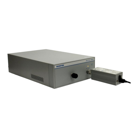
Introduction The 55 series wideband USB power sensors are the latest series of products from Boonton Electronics that turn your PC or laptop using a standard USB 2.0 port into a state of the art power meter without the need for any other instrument. -
Page 4: Technical Specifications Of Boonton 55 Series Wideband Usb Sensor
55 Series Wideband USB Sensor Technical Specifications of Boonton 55 Series Wideband USB Sensor Page 4 of 28... -
Page 5: Safety Summary
Boonton Electronics for repair to insure that the warranty and safety features are maintained Getting Started Before you start, make sure you have the following items in your 55 series USB Power Sensor package: • Boonton 55 Series Wideband USB Power Sensor •... -
Page 6: Installing Boonton Power Analyzer Suite Software
55 Series Wideband USB Sensor Installing Boonton Power Analyzer Suite Software This section describes the installation and use of Boonton Power Analyzer Suite software for 55 series wideband USB sensors. Before you start, check your PC for software compatibility. Caution: Do not connect the power sensor to your PC until you have installed the Boonton Power Analyzer software. - Page 7 (5) Once IVI Shared Components installation is completed, then Microsoft DirectX setup wizard will appear and will guide you through the installation process. (6) Now Boonton Peak Analyzer Suite software installation wizard will appear. Select "Run" in order to continue with the installation process.
- Page 8 55 Series Wideband USB Sensor (8) By default software will be installed at C:\Program Files (x86)\Boonton\Peak Power Analyzer Suite\ . (9) Start the installation process by following windows wizard instructions, accepting license agreement and click several buttons. This will install all necessary driver files and required DLL files.
-
Page 9: Connecting Sensors To The Pc
Connecting Sensors to the PC Connect the Boonton 55 series USB sensor to your PC through the supplied USB cable. The power sensor is USB 2.0 compatible. It is recommended that you use the USB cable supplied with your sensor. -
Page 10: Rf Power Measurements
Boonton Power Analyzer Suite software. NOTE: 55 Series USB driver file is provided by Boonton Electronics and digitally signed by Microsoft Corporation. (1) Open Boonton Power Analyzer Suite by double clicking on the desktop icon . - Page 11 Docking Windows: Boonton Power Analyzer Suite uses dockable windows to allow the user to arrange the various windows in the configuration of their choice. You can drag a docked window by clicking its title bar. This action enables you to move the window to a different docked position or undock it.
- Page 12 The following diagram shows the guide diamonds with arrows that appear when you drag a tool window toward the center of the Boonton software main window. The diamond on the right edge only appears when you drag a tool window toward the edge of the software.
- Page 13 55 Series Wideband USB Sensor The Main Toolbar: The software provides a main toolbar that is located at the top of the main program window and hosts shortcuts to commonly used functions and measurements. Making Pulse Measurement: In order to display a pulse measurement user need to select icon from the main toolbar.
- Page 14 Figure : Main application window of Boonton Power Analyzer Suite for pulse signal measurement. Boonton Power Analyzer software allows to use custom entry fields for most numeric data under both Channel Control View and Time/Trigger View. These entry fields are closely related to regular text entry boxes that allow the user to enter any number.
- Page 15 55 Series Wideband USB Sensor User can also perform zoom feature in details be selecting four options from the lower toolbar of the trace window. Available options for zoom are: Horizontal & Vertical, Horizontal, Pan and None with Undo and Redo selections.
- Page 16 55 Series Wideband USB Sensor Channel: You can select an individual or all channels (for multi-channels) by using drop down list. Sensor model with serial number and firmware version displayed under this channel parameter. Multi-Channel: Simultaneous measurement of multiple channels can be performed by selecting from drop down list.
- Page 17 Time base: Boonton software uses a fixed grid of 10 divisions for the time-scale. The time resolution is set per division with the lowest possible value of 5 ns/div.
- Page 18 55 Series Wideband USB Sensor Marker Settings: Marker settings will allow you to change both marker 1 and marker 2 positions by using either arrow keys or entering numerical values into the field. It will also display the delta value between two markers.
- Page 19 55 Series Wideband USB Sensor Automatic Measurements: Selecting icon will allow you to display a tabulated field with a list of parameters for a RF pulse measurements including marker measurements. Below is an example screenshot for automatic parameters displayed for a pulse measurements.
- Page 20 55 Series Wideband USB Sensor Display Settings: This option allows user to select different trace and graph colors for multiple channels including color options by selecting both enable/disable features for Average, Envelope, Maximum and Minimum trace of the measurement. It is also possible to adjust marker color, background, grid colors and more under "Graph Colors"...
- Page 21 55 Series Wideband USB Sensor Statistical Measurement: For statistical measurements, user need to select icon from menu bar to view a CCDF graph. The sidebar on CCDF screen will allow user to customize the horizontal scale, horizontal offset, cursor type, cursor position and dB offset. User can also enable/disable capture including reset for that.
-
Page 22: Remote Programming
Windows 8.1 it is under This PC > Local Disk (C:) > Program Files (x86)\IVI Foundation\IVI\Drivers\Btn55xxx. Also the same IVI driver document file can be downloaded from Boonton product page. Here is the link: http://boonton.com/~/media/Boonton/Manuals%20and%20Software/Boonton%2055%20Series%20API%20Progra mming%20Reference.ashx Fig.: Example screenshot (Windows 7 OS). Shortcut Fig.: For Windows 8.1, shortcut icons can be found on... -
Page 23: Software Upgrade
Firmware Upgrade Device firmware has been loaded into the 55 Series USB Power sensor at the factory. This consists of the proprietary System software and the 55 Series Application Firmware. The Application Firmware for the device will be updated from time to time to correct errors and add new features. Users can upgrade their firmware by downloading a special Firmware Upgrade package with instruction from the Boonton Electronics official webpage, http://www.boonton.com/service-and-support/software-and-drivers... -
Page 24: Troubleshooting
55 Series Wideband USB Sensor Inspection: If a 55 Series power sensor malfunctions, perform a visual inspection of the instrument. Inspect for signs of damage caused by excessive shock, vibration or overheating. Inspect for broken or damaged connection port at sensor head, or accumulations of dust or other foreign matter. - Page 25 55 Series Wideband USB Sensor If this is NOT the driver listed in your Device Manager, then use the following procedure to remove the installed driver and configure the correct driver: Device driver software was not successfully installed In the event of device driver software was not installed successfully, try the following: ...
- Page 26 55 Series Wideband USB Sensor USB Port cannot supply 500 mA Usually a USB 2.0 port is capable of supplying 500 mA current through its port. If the event of a power supply issue with USB 2.0 port, you can verify the actual rating by visiting Device Manager > USB Controllers > Generic USB Hub and then right click and check the properties windows under "Power"...
-
Page 27: Repair Policy
Note that sensors which have failed due to overloading, improper mating, or connecting to an out-of-tolerance connector are not considered defective and will not be covered by the Boonton Warranty. If the Boonton 55 Series RF Power Sensor is not operating correctly and requires service, contact the Boonton Electronics Service Department for return authorization. -
Page 28: Contact And Support
55 Series Wideband USB Sensor Contact and Support To contact Boonton please contact your local representative or use the following e-mail address, phone or fax: Boonton Electronics 25 Eastmans Road Parsippany, NJ 07054 United States Phone: +1 (973) 386-9696 Fax:...
Need help?
Do you have a question about the 55318 and is the answer not in the manual?
Questions and answers