Table of Contents
Advertisement
Advertisement
Table of Contents

Related Manuals for ABB Inline II ZHBM00


Summarization of Contents
1 Product Overview - Slimline Variants
1.1 Slimline XRGOO
Description of the Slimline XRGO0 product.
1.2 Slimline XRG1
Description of the Slimline XRG1 product.
1.3 Slimline XRG2 and XRG3
Description of Slimline XRG2 and XRG3 products.
1 Product Overview - Inline II Variants
1.4 Inline II ZHBM00
Description of the Inline II ZHBM00 product.
1.5 Inline II ZHBM123
Description of the Inline II ZHBM123 product.
1 Product Overview - Standalone and ITS2.1 Interface
1.6 Standalone ITS
Description of the Standalone ITS product.
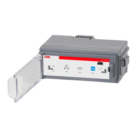
1.7 ITS2.1 Overview
Overview of the ITS2.1 unit, its components, and indicators.
TEST/Prg Connection and Usage
Details on the TEST/Prg port for configuration and its proper use.
LED Indicators and Modes
Explains the behavior of Power, Communication, Fuse Blown, and Local/Remote LEDs.
1.8-1.10 Prerequisites and Setup Tools
1.8 Prerequisites
Important warnings and requirements before connecting the ITS unit.
1.9 Download and Install Ekip Connect Software
Steps to download and install the necessary Ekip Connect software.
1.10 Ekip T&P Test and Programming Unit
Details on the Ekip T&P unit for testing and programming the ITS2.1.
2 Ekip Connect Software Operations
2.1 Starting Ekip Connect and Updates
Guide to launching Ekip Connect and checking for the latest software updates.
3 Basic Parameter Setting
Key Configuration Parameters
Essential parameters like Switch type and Nominal Line Voltage to configure for ITS2.1.
3 ITS2 Configuration Details
Preventive Overload Protection Settings
Configuration options for preventive overload protection handling.
Fuse Blown Handling Settings
Configuration options for fuse blown handling.
ITS Status and Display Options
Configuration of ITS status, display, and custom fields.
4 Additional Parameter Settings
Modbus RTU Communication Configuration
Settings for Modbus RTU communication parameters.
Ekip COM Modbus TCP IP Settings
Configuration of static IP address for Ekip COM Modbus TCP module.
4 Detailed Parameter Settings
Fuse Blown Switch Open
Configuration for fuse blown switch open functionality for motor-operated devices.
Preventive Overload Protection
Configuration for enabling and setting limits for overload protection.
ITS Status and Custom Fields
Setting operating mode, LED mode, and custom fields for ITS status.
5 ITS Values and Status Information
5.1 Main Page - Product Details
Displays product details like serial number, firmware, and rated current.
5.1 Main Page - Currents and Commands
Shows measured currents (L1, L2, L3) and command options.
ITS Status Indicators
Explains status indicators like Supply, Operating Mode, and LED Alive.
5 Switch and Status Information
Switch Information Details
Details on switch type, position, and operation counts.
ITS Status Indicators Explained
Detailed meanings of ITS status indicators like Supply from Vaux, Local/Remote mode.
5.2 Alarms Overview
Alarm Descriptions
Explanation of various alarms including preventive overload, fuse blown, and CRC errors.
5.3 All Measures - Currents, Voltages, Energies
Current Measurements
Actual measurements for L1, L2, L3 currents.
Voltage Measurements
Actual phase (V1N, V2N, V3N) and line (V12, V23, V31) voltages.
Energy Measurements
Measurements for active, reactive, and apparent energy.
5.4 Main Measures
Status Indicators
Displays switch status (open/closed) and fuse blown status.
Main Measurement Data
Shows actual currents, voltages, powers, and temperature.
5.5 Min-Max Measures
Current and Voltage Min-Max
Minimum and maximum values for currents and voltages.
Power and Other Min-Max
Minimum and maximum values for powers, frequency, and temperature.
5.6 Modbus RTU Configuration
Modbus RTU Communication Settings
Configuration of slave address, baud rate, and protocol type.
Modbus Communication Statistics
Statistics on received and sent Modbus messages.
5.7 Modbus TCP Configuration
Ekip COM Modbus TCP Information
Details on serial number, firmware versions, and MAC address.
Network Settings
Configuration of IP address, subnet mask, and gateway address.
6 Multiplug Terminal Connections
6.1 Slimline XRG/Inline II Multiplug
Terminal pin definitions for multiplug on Slimline XRG and Inline II ZHBM.
6.2 Standalone ITS Multiplug
Multiplug to User Side
Terminal pin definitions for user side multiplug on standalone ITS.
Other Signals/Voltage Multiplug to Switch
Terminal pin definitions for switch side signals and voltage inputs.
7 Modbus RTU Details
7.1 Modbus Telegram Mapping
Mapping of parameters to Modbus addresses for data reading.
7.2 Modbus RTU Troubleshooting
Methods for troubleshooting Modbus RTU communication issues.
7.3 Modbus RTU Cabling
7.3.1 Terminating Resistors (TR)
Requirements for 120 Ohm terminating resistors to prevent signal reflection.
7.3.2 Grounding of Shielding
Guidelines for connecting the cable shield to ground for signal integrity.
8 Ekip COM Modbus TCP Module
Module Functionality and LEDs
Description of module's communication capabilities and LED indicators.
9 Cyber Security
Security Disclaimer and Responsibilities
Customer responsibility for securing the connection and data.
Secure Deployment Recommendations
Best practices for secure network positioning and physical access control.
10 Power Direction Setting
10.1 Slimline XRG Power Direction
Setting power direction for Slimline XRG via fuse board straps.
10.2 Inline II ZHBM Power Direction
Setting Power Direction
How to set power direction for Inline II ZHBM using jumpers.
10.3 Power Direction for Other Switches
Connecting Voltage Cables
Connecting phase voltage cables to the standalone ITS for power direction.
11 Technical Data
ITS2.1 Specifications
Key technical specifications including voltage, current, temperature, and accuracy.
Modbus Communication Settings
Default settings for Modbus communication like baud rate and address range.
12 Reference Documentation
Installation Instructions
References to specific installation guides for different product variants.
Application Papers
References to technical application papers for bus communication.
13 XR ITS2.D with Ekip Display
13.1 How to Plug in the Ekip Display
Step-by-step instructions for physically connecting the Ekip Display unit.
14 Ekip Display Features
14.1 Power LED Behavior
How the Ekip Display's power LED mirrors the ITS2 unit's power status.
14.2 Front Overview and Controls
Description of the Ekip Display's front panel layout and available controls.
14.3 Ekip Display Start Menu Icons
Status Icon Alternatives
Explanation of icons representing communication status and device states.
XR MOT/Manual Operation Icons
Icons for fuse status, voltage, and motor operation modes.
14.4 Ekip Display Signaling Area
Signaling Area Icon Descriptions
Detailed meanings of icons shown in the signaling area for various conditions.
14.5 Ekip Display Navigation
Navigation Tree and Keys
Illustrates the navigation tree and key combinations for menu interaction.
15 Troubleshooting
Fault Analysis and Resolution
Common faults, their analysis, and corresponding troubleshooting methods.
Need help?
Do you have a question about the Inline II ZHBM00 and is the answer not in the manual?
Questions and answers